
Apparatus and method for controlling intake air amount of internal combustion engine

a technology of intake air and internal combustion engine, which is applied in the direction of electric control, machines/engines, output power, etc., can solve the problem of insufficient intake air, and achieve the effect of high accuracy and throttle-less operation

Inactive Publication Date: 2005-03-08
HITACHI LTD
View PDF3 Cites 10 Cited by
  • Summary
  • Abstract
  • Description
  • Claims
  • Application Information

AI Technical Summary

Benefits of technology

This approach enables precise control of intake air amount, achieving high-accuracy throttle-less operation by considering the 'valve lift amount-intake amount characteristic', thereby ensuring the requested intake air amount is met while maintaining efficient engine operation.

Problems solved by technology

Therefore, it has been found that, in order to ensure an intake air amount requested according to an engine operating condition, the control of intake valve closing timing as in the conventional technique is not enough, and the valve operating characteristic needs to be set, considering the “valve lift amount-intake amount characteristic”, that is, the influence of the valve lift amount on the intake amount.

Method used


Image

  • Apparatus and method for controlling intake air amount of internal combustion engine
  • Apparatus and method for controlling intake air amount of internal combustion engine
  • Apparatus and method for controlling intake air amount of internal combustion engine

Examples


Embodiment Construction

An embodiment of the present invention will be described based on the drawings.

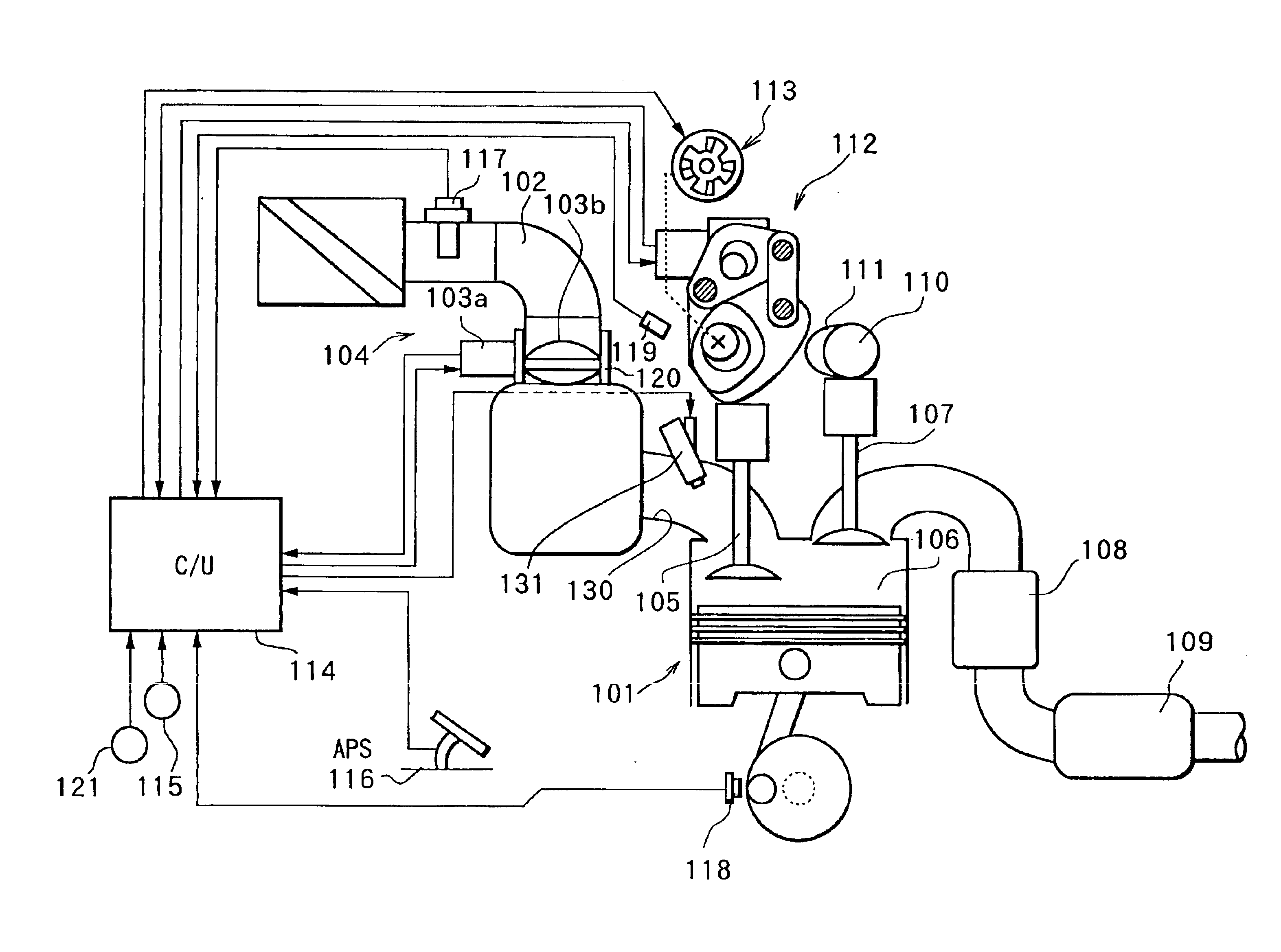
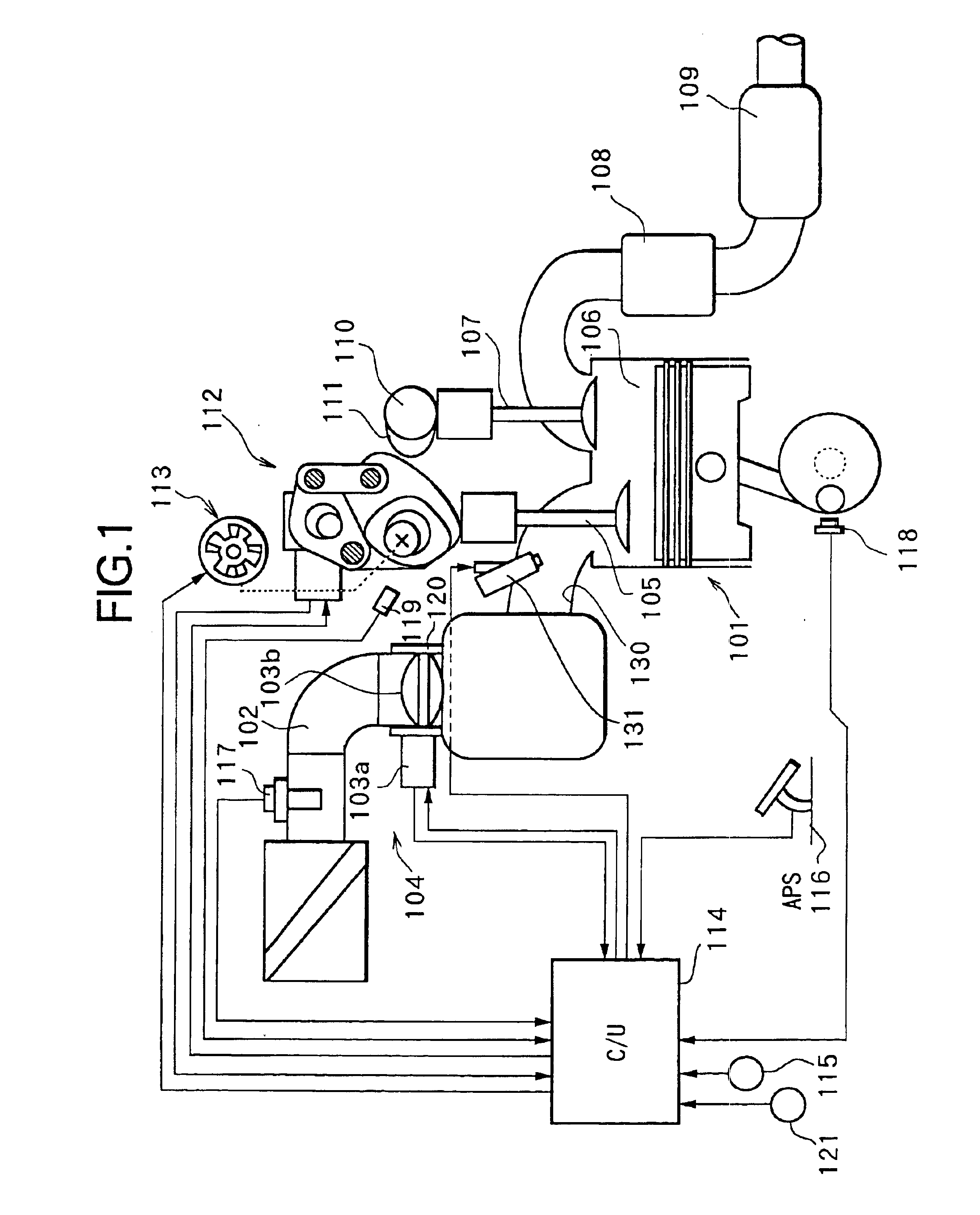
FIG. 1 is a structural diagram of an internal combustion engine for vehicle. In FIG. 1, in an intake passage 102 of an internal combustion engine 101, an electronically controlled throttle 104 is disposed for driving a throttle valve 103b to open and close by a throttle motor 103a. Air is sucked into a combustion chamber 106 via electronically controlled throttle 104 and an intake valve 105.

A combusted exhaust gas is discharged from combustion chamber 106 via an exhaust valve 107, purified by an exhaust purification catalyst 108, and then emitted into the atmosphere via a muffler 109.

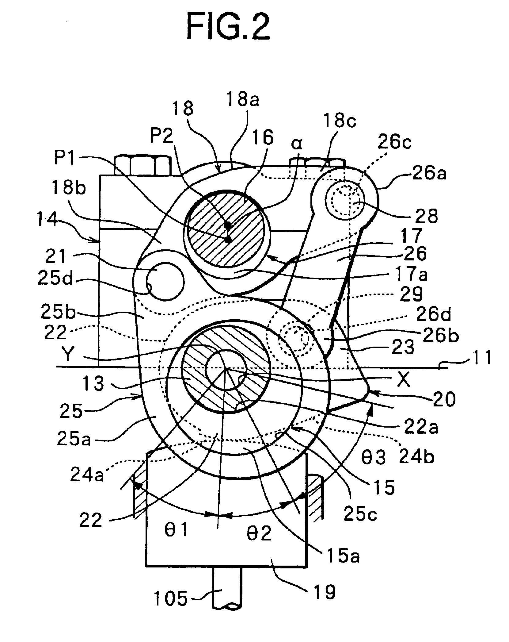
Exhaust valve 107 is driven by a cam 111 axially supported by an exhaust side camshaft 110, while keeping a valve lift amount and a valve operating angle thereof constant. On the contrary, a valve lift amount and a valve operating angle of intake valve 105 are successively varied by a VEL (Variable valve Event and Lift mechan...


PUM


Abstract

In an internal combustion engine provided with a variable valve mechanism that varies at least a valve operating characteristic (valve lift amount and the like) of an intake valve, a target intake air amount equivalent to a target torque is set based on operating conditions of the engine, to calculate a target volume flow ratio by dividing the target intake air amount by an engine rotation speed and total cylinder volume. The target volume flow ratio is corrected according to closing timing of the intake valve. If the valve lift amount of the intake valve is in a low valve lift region, the target volume flow ratio is further corrected according to the valve lift amount, and the post corrected target volume flow ratio is converted into a valve opening area of the intake valve to be set as a target valve opening area. Then, based on the target valve opening area, a target valve operating characteristic of the intake valve is set. Thereafter, the variable valve mechanism is controlled so that the valve operating characteristic of the intake valve reaches the target valve operating characteristic.

Description

FIELD OF THE INVENTIONThe present invention relates to a technique for controlling an intake air amount by a variable valve mechanism, which varies an operating characteristic of an intake valve of an engine.RELATED ART OF THE INVENTIONHeretofore, there has been known a control apparatus, as disclosed in Japanese Unexamined Patent Publication No. 2001-271665, which controls an operating characteristic of an intake valve to thereby control an intake air amount (perform a so-called throttle-less operation).In such a control apparatus, a target torque is calculated according to an engine operating condition and also a torque fluctuation amount of the engine is detected, and intake valve closing timing and a valve overlap amount of intake / exhaust valves are set so that an internal EGR rate becomes maximum within an allowable range of the torque fluctuation amount, thereby realizing the throttle-less operation which achieves both the intake air amount control and the reduction of emissio...

Claims


Application Information

Patent Timeline
Patent Type & Authority Patents(United States)
IPC IPC(8): F02D41/00F02D13/02F01L1/344F01L1/34F01L13/00F01L1/18F02D41/04F02D45/00
CPCF01L1/34F01L1/3442F01L13/0026F02D13/0211F02D13/0261F02D41/0002F01L2001/0537F01L2013/0073Y02T10/42F02D2041/001Y02T10/18F01L2800/00Y02T10/12Y02T10/40
Inventor IIZUKA, ISAMUMACHIDA, KENICHI
Owner HITACHI LTD
Learn More