Control device for internal combustion engine

a control device and internal combustion engine technology, applied in the direction of electric control, combustion-air/fuel-air treatment, machines/engines, etc., can solve the problems of low estimation accuracy of affecting the accuracy of estimating the intake valve flow rate using the intake valve model equation, and affecting the accuracy of estimating the intake valve flow rate. , to achieve the effect of high accuracy, low cost and reduced errors included in learned values of respective parameters

Active Publication Date: 2017-02-02
TOYOTA JIDOSHA KK
View PDF1 Cites 3 Cited by
  • Summary
  • Abstract
  • Description
  • Claims
  • Application Information

AI Technical Summary

Benefits of technology

This patent describes a control device for an internal combustion engine that can improve the accuracy of estimating the flow rate of air entering the engine. The device can learn parameters that affect the flow rate error under different operating conditions, such as acceleration, steady-state running, and high engine load. By using these learned parameters, the control device can reduce errors in the estimation of the flow rate, even under extreme operating conditions. The control device can also adjust the timing of the intake and exhaust valves to optimize engine performance.

Problems solved by technology

However, in some cases, due to manufacturing errors in components of an internal combustion engine or to aged deterioration thereof, a deviation can arise between a relation between an intake pipe pressure and an intake valve flow rate that is assumed in the intake valve model equation and the actual relation therebetween.
Such a deviation lowers the estimation accuracy for the intake valve flow rate.
However, with respect to operating conditions that are temporarily selected during transient operation, because the coefficients of the intake valve model equation are not subjected to much adjustment, a decrease in the estimation accuracy with respect to the intake valve flow rate is liable to occur due to aged deterioration of components of the internal combustion engine.
That is, with the technique described in JP2007-211747A, there is the problem that an error depending on the selection frequency of the operating conditions arises in the accuracy of estimating the intake valve flow rate using the intake valve model equation.
If an error arises between the aforementioned two relations, it is considered that a manufacturing error or aged deterioration is present in some component or other of the internal combustion engine (particularly, a component that affects the intake valve flow rate).
As the result of extensive studies conducted by the inventor of the present application it was found that the above described intake valve flow rate error is caused by a deviation from a design value of the following four physical quantities: an intake valve working angle, an exhaust valve working angle, an intake valve timing and an exhaust pressure loss.
A manufacturing error or aged deterioration of a component of an internal combustion engine that affects the relation between an intake pipe pressure and an intake valve flow rate results in a deviation from a design value of any one of these four physical quantities.
Further, it was also found that the respective influences of the first to fourth parameters on the intake valve flow rate error depend on state quantities of the internal combustion engine including at least the engine speed and the intake pipe pressure.

Method used


Image

  • Control device for internal combustion engine
  • Control device for internal combustion engine
  • Control device for internal combustion engine

Examples


Embodiment Construction

[0030]An embodiment of the present invention is described hereunder with reference to the accompanying drawings. However, it is to be understood that even when the number, quantity, amount, range or other numerical attribute of an element is mentioned in the following description of the embodiment, the claimed invention is not limited to the mentioned numerical attribute unless expressly stated or theoretically defined. Further, descriptions of, e.g., structures or steps in conjunction with the following embodiment are not necessarily essential to the claimed invention unless expressly stated or theoretically defined.

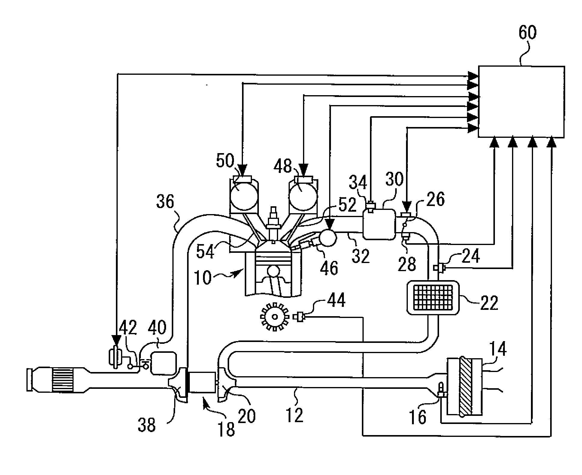
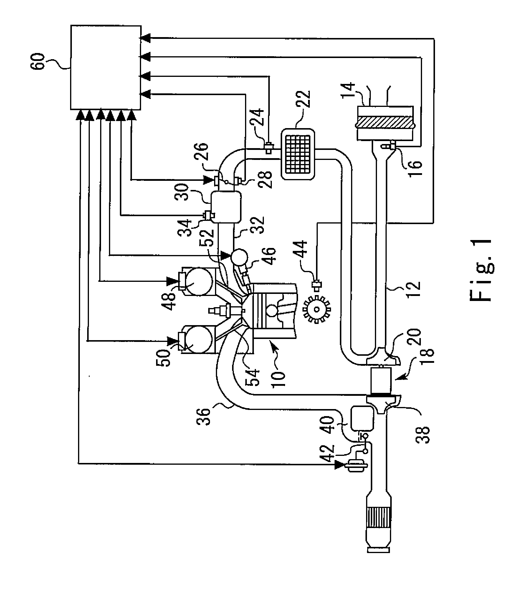
[0031]FIG. 1 is a schematic diagram illustrating the configuration of an internal combustion engine that is controlled by a control device of the present embodiment. An internal combustion engine (hereunder, referred to as simply “engine”) 10 according to the present embodiment is configured as a spark-ignition engine that is mounted in a vehicle. However, the number of...


PUM


Abstract

Respective learned values of four parameters, that are an intake valve working angle deviation amount, an exhaust valve working angle deviation amount, an intake valve timing deviation amount and an exhaust pressure loss deviation amount, are calculated based on learned values of an intake valve flow rate error that are obtained under at least four different operating conditions. A correction amount with respect to an intake valve flow rate that is calculated with an intake valve model equation is calculated based on respective learned values of the four parameters using an intake valve flow rate error model equation in which coefficients are represented by functions of state quantities of an engine that include an engine speed and an intake pipe pressure.

Description

CROSS-REFERENCE TO RELATED APPLICATION[0001]The present application claims priority to Japanese Patent Application No. 2015-148796 filed on Jul. 28, 2015, which is incorporated herein by reference in its entirety.BACKGROUND[0002]Field of the Disclosure[0003]The present disclosure relates to a control device for an internal combustion engine that estimates an intake valve flow rate based on an estimated value or a measured value of an intake pipe pressure using an intake valve model equation in which an intake valve flow rate is represented by a linear expression that adopts an intake pipe pressure as a variable.[0004]Background Art[0005]As described in JP2007-211747A, an intake valve flow rate that is a flow rate of air that passes through an intake valve and enters a cylinder can be represented by a linear expression that adopts an intake pipe pressure that is a pressure in a space from a throttle to the intake valve as a variable. This linear expression is referred to as an “intak...

Claims


Application Information

Patent Timeline
Patent Type & Authority Applications(United States)
IPC IPC(8): F02D41/24F02D41/14F02D41/00F02M35/10
CPCF02D41/2464F02M35/10386F02M35/1038F02D2041/001F02D41/0007F02D2200/0402F02D41/1448F02D13/0207F02D41/18F02D41/182F02D41/2445F02D41/248F02D2200/0406
Inventor TANAKA, SATORU
Owner TOYOTA JIDOSHA KK
Why Eureka
Try Eureka