
Energy harvesting circuits and associated methods

a technology of energy harvesting circuit and energy harvesting circuit, which is applied in the field of inherently tuned antennas, can solve the problems of lack of stability, increase complexity and cost, and do not teach how to achieve the

Inactive Publication Date: 2005-02-15
PITTSBURGH UNIV OF
View PDF48 Cites 702 Cited by
  • Summary
  • Abstract
  • Description
  • Claims
  • Application Information

AI Technical Summary

Benefits of technology

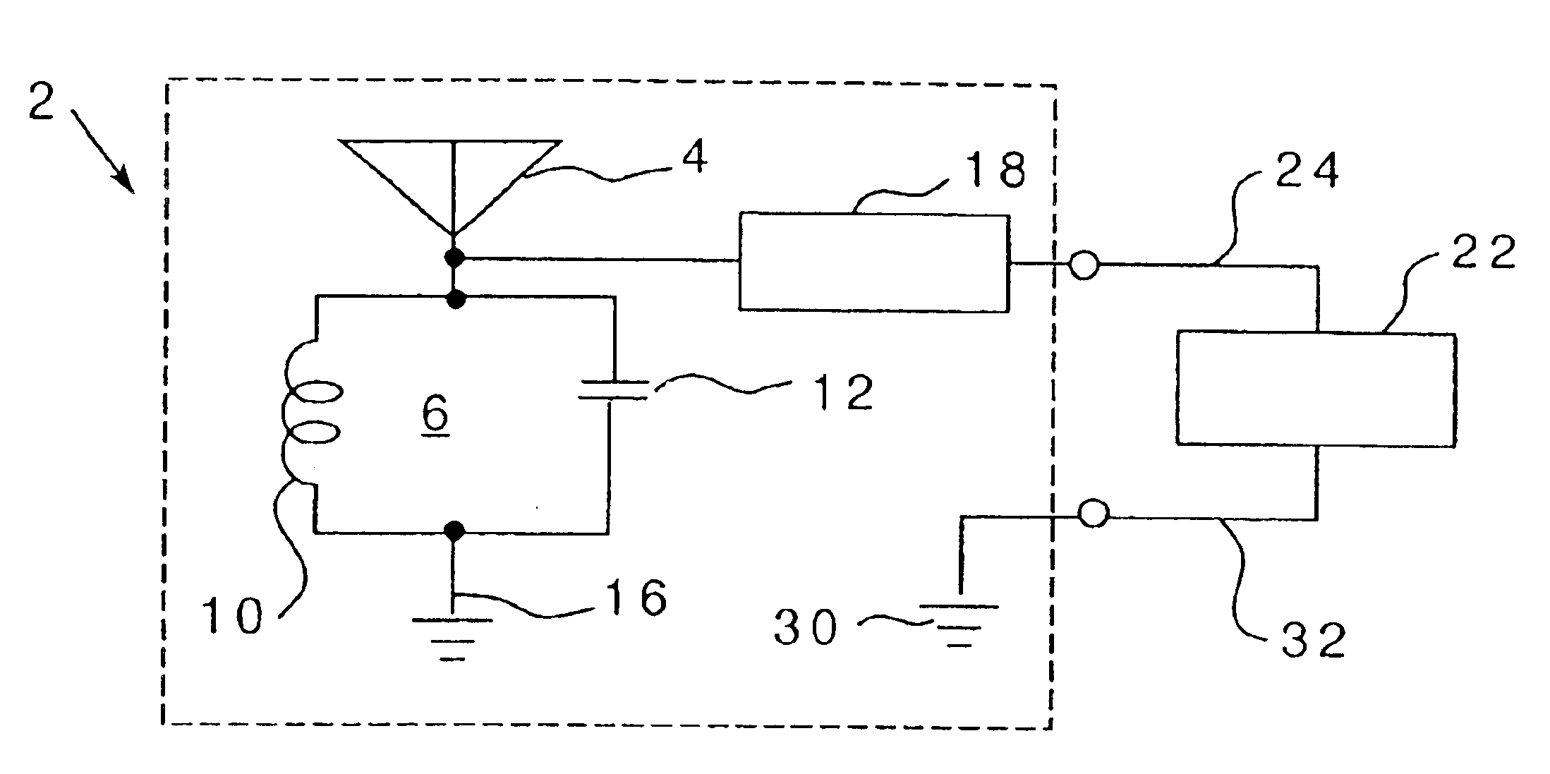
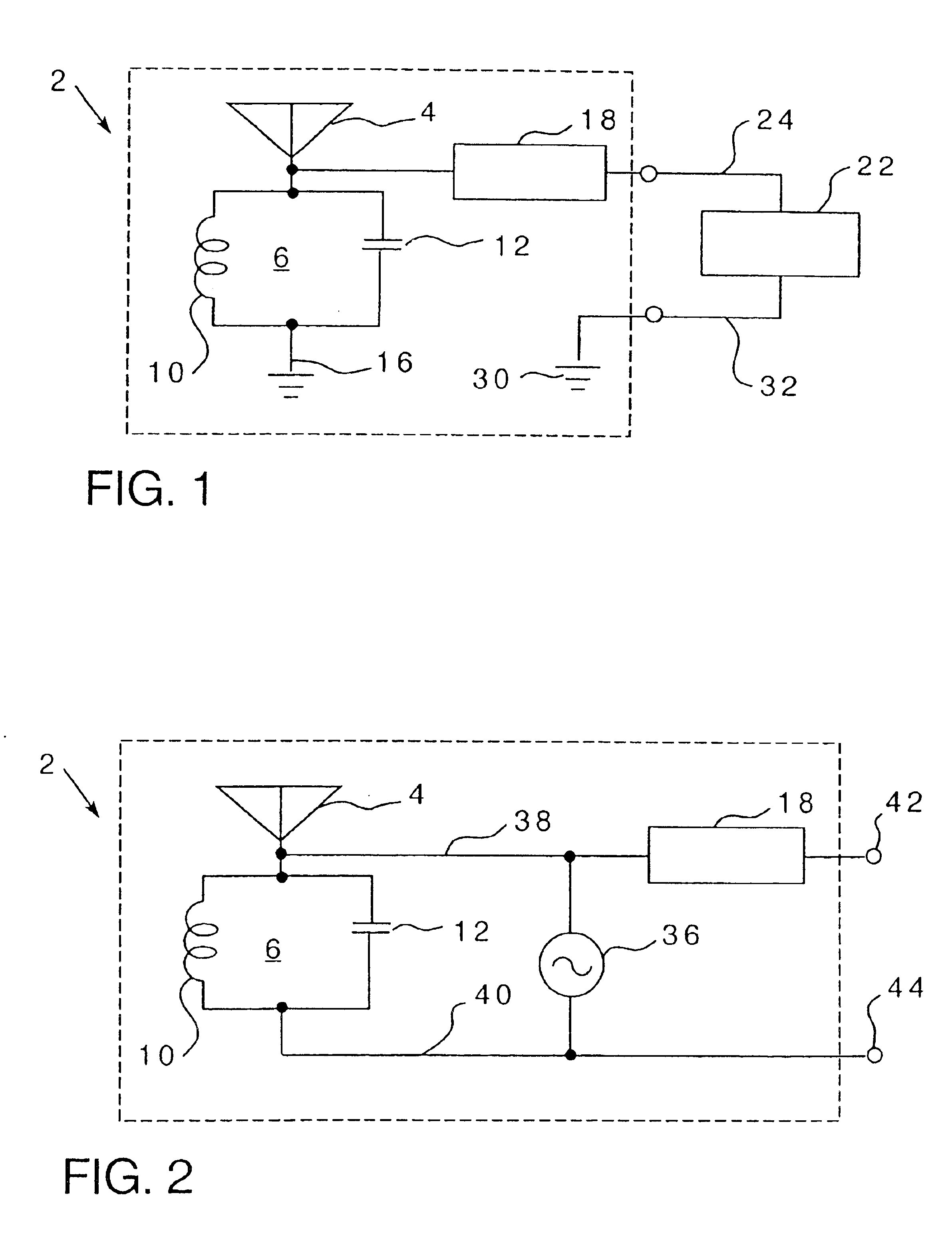
It is a further object of the present invention to provide such circuits which can advantageously be employed with RF energy which is transported through space and received by the energy harvesting circuitry.

Problems solved by technology

These prior disclosures, while discussing the physical phenomenon, do not teach how to achieve the effect.
For example, wind-induced motion of the antenna causing antenna impedance variation were said to be the source of a lack of stability with the circuit going into oscillation responsive thereto.
With respect to smaller antennas, the addition of discrete circuit components to provide regeneration increases complexity and costs and, therefore, does not provide an ideal solution, particularly in respect to small, planar antennas on a substrate such as an integrated circuit chip such as a CMOS chip, for example.
One of the problems with this approach is the need to fabricate small, air core inductors of sufficiently high inductance and Q for integrated circuit applications.
Such an approach increases the complexity and cost of the antenna on a chip and also limits the ability to reduce the size of the antenna because of the need for the magnetic film layers between the antenna coils.

Method used


Image

  • Energy harvesting circuits and associated methods
  • Energy harvesting circuits and associated methods
  • Energy harvesting circuits and associated methods

Examples


example 1

It will be appreciated that the invention is suited for use with extremely small circuits which may be provided on integrated circuit chips. Assuming, for example, energy harvesting at a radio frequency (RF) of 915 MHz, the effective area of an antenna normally does not get smaller than k×82 with k being less than or equal to 1 that is a wavelength of the given frequency (8) on a side. For example, if the antenna is a typical half-wave dipole, the effective area is not much smaller than 82. At 915 MHz, the wavelength 8 is approximately 12.908 inches and, as a result, the k 82 of a half-wave dipole for energy harvesting would be 21.66 square inches with k equal to 0.13. The half-wave characterization implies something about the dimensions of the antenna. However, the physical dimension of the antenna employable advantageously with the present invention would be substantially less than 21.66 square inches.

As a second example, a quarter-wave “whip” antenna having an effective area of 0...

example 2

In order to provide a further comparison, one may consider a test antenna which is 1560 micron square in a planar antenna on a CMOS chip as the test antenna. The antenna was designed to provide a full conductive path over a quarter of a cycle of a 915 MHz current, i.e., a quarter of a wavelength. The test antenna employed in the experiments had a square spiral of a length of approximately 3.073 inches, wherein the spiral is formed within a square of 1560 microns. As a result, the length of the conductor is one quarter wavelength, but it does not appear as the traditional quarter wave whip antenna. The 1560 micron dimension establishes a physical antenna area microns is 0.061417 inches, thereby providing a physical area of the spiral antenna of 0.00377209 inches.

In establishing the square spiral, the material employed was made up of a conductive coil of aluminum with a square resistance of 0.03 ohms. The conductive coil was put on the substrate as part of the AMI_ABN—1.5:CMOS process...


PUM


Abstract

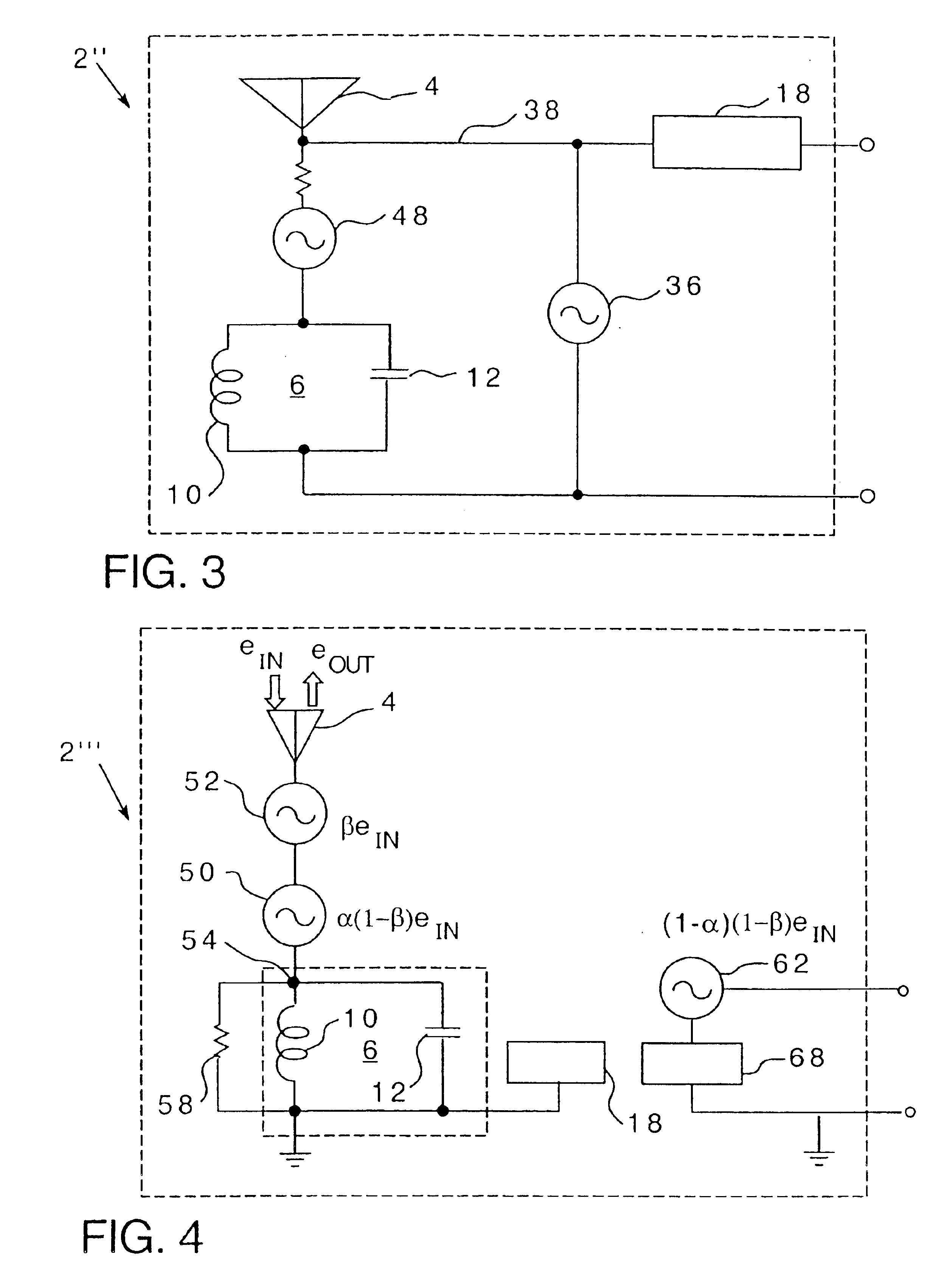
An inherently tuned antenna has a circuit for harvesting energy transmitted in space and includes portions that are structured to provide regenerative feedback into the antenna to produce an inherently tuned antenna which has an effective area substantially greater than its physical area. The inherently tuned antenna includes inherent distributive inductive, inherent distributive capacitive and inherent distributive resistive elements which cause the antenna to resonate responsive to receipt of energy at a particular frequency and to provide feedback to regenerate the antenna. The circuit may be provided on an integrated circuit chip. An associated method is provided.

Description

BACKGROUND OF THE INVENTION1. Field of the InventionThe present invention relates to an inherently tuned antenna having circuit portions which provide regenerative feedback into the antenna such that the antenna's effective area is substantially greater than its physical area and, more specifically, it provides such circuits which are adapted to be employed in miniaturized form such as on an integrated circuit chip or die. Associated methods are provided.2. Description of the Prior ArtIt has long been known that energy such as RF signals can be transmitted through the air to various types of receiving antennas for a wide range of purposes.Rudenberg in “Der Empfang Elektricscher Wellen in der Drahtlosen Telegraphie” (“The Receipt of Electric Waves in the Wireless Telegraphy”) Annalen der Physik IV, 25, 1908, pp. 446-466 disclosed the fact that regeneration through a non-ideal tank circuit with a ¼ wavelength whip antenna can result in an antenna having an effective area larger than i...

Claims


Application Information

Patent Timeline
Patent Type & Authority Patents(United States)
IPC IPC(8): H01Q1/22H01Q1/24H01Q9/27
CPCH01Q1/22H01Q1/248H01Q1/2225
Inventor MICKLE, MARLIN H.CAPELLI, CHRISTOPHER C.SWIFT, HAROLD
Owner PITTSBURGH UNIV OF
Learn More