
Method of estimating temperature and device for the effecting same

a technology of estimating temperature and estimating device, which is applied in the direction of heat measurement, electric controller, instruments, etc., can solve the problems of inability to measure the physical characteristic showing a distinct temperature dependence, the inability to predict the failure of the temperature sensor, and the inability to measure the physical characteristic. , to achieve the effect of small heat capacity, rapid temperature change, and easy estimation of temperatur

Inactive Publication Date: 2005-02-15
TOYOTA JIDOSHA KK
View PDF28 Cites 42 Cited by
  • Summary
  • Abstract
  • Description
  • Claims
  • Application Information

AI Technical Summary

Benefits of technology

With this modification, it is possible to determine the temperature increment quantity )T from the specific value that substantially indicates the amount of energization and to easily estimate the temperature of either of the first or second object by using this.
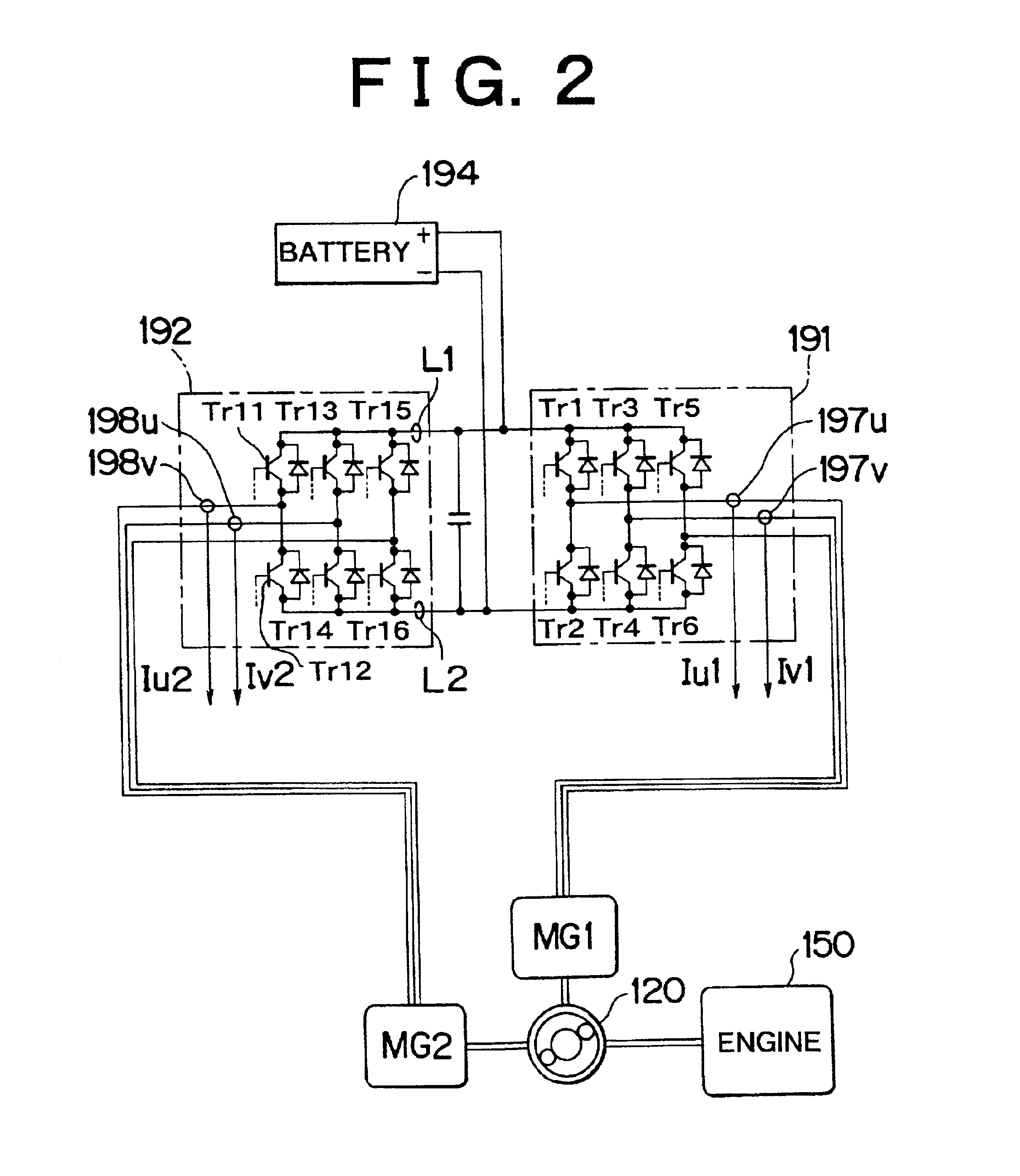
Normally, the power semiconductor element has a very small heat capacity and shows a rapid temperature change. Therefore, it is possible to easily estimate the temperature of either the power semiconductor element or the coolant from the specific value that substantially indicates the amount of energization of the power semiconductor element and the coolant temperature.

Problems solved by technology

However, there is a case where it is necessary to check the temperature of a region in which no temperature sensor can be installed directly.
Moreover, the probability of the temperature sensor failure is likely to become higher as the number of the sensors increases.
However, depending on the kind of the region to be estimated, there may be a case where a physical characteristic showing a distinct temperature dependence cannot be measured.
Or there may be a case where, although the measurement of such a physical characteristic is feasible, its measurement is not desired because of the need to reduce the number of sensors.

Method used


Image

  • Method of estimating temperature and device for the effecting same
  • Method of estimating temperature and device for the effecting same
  • Method of estimating temperature and device for the effecting same

Examples


modified example 1

H1. Modified Example 1

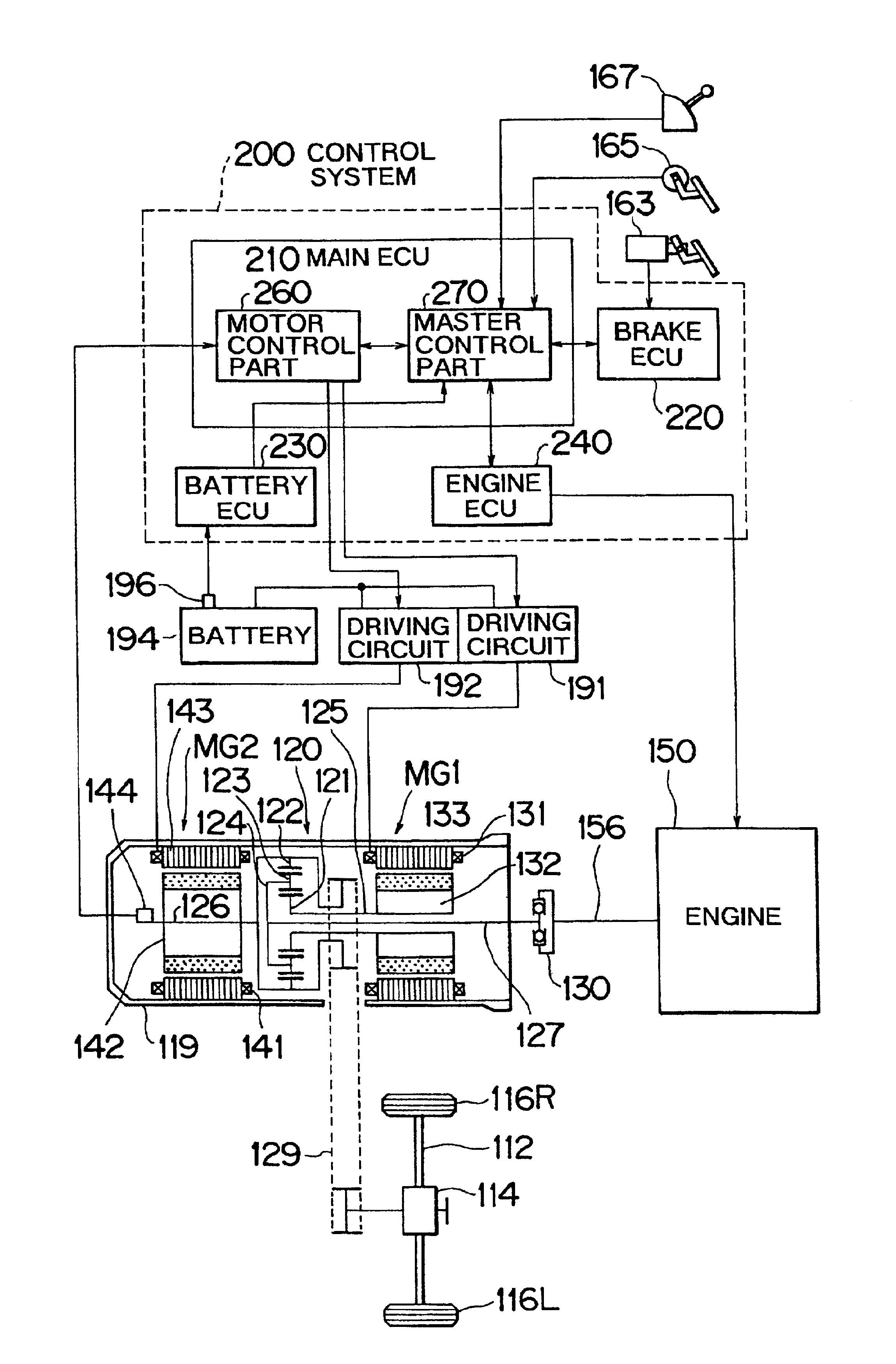
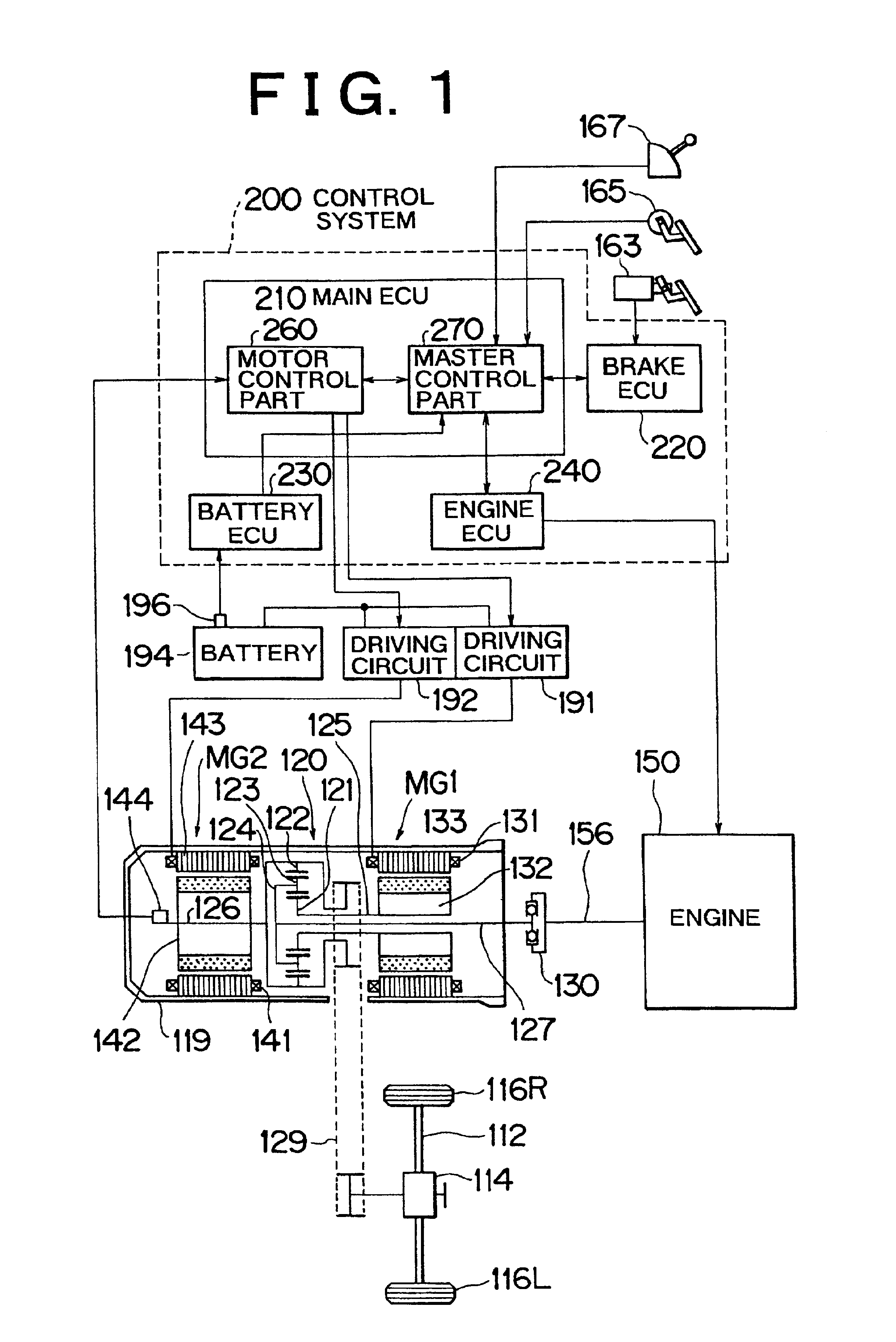
In the embodiments, the hybrid vehicle of the so-called mechanical distribution type where the power of the engine is distributed to both the axle shaft and the first motor MG1 with the use of the planetary gear. However, the invention may be applied to the hybrid vehicle of the so-called electric distribution type where the power of the engine is distributed electrically with the use of the motor / generator, without using a planetary gear. The hybrid vehicle of the electric distribution type is disclosed by, for example, Japanese Patent Laid-open Publication No. H9-46965 applied by the present inventors. Accordingly its explanation will be omitted.

Further, the invention can be applied to other vehicles than hybrid vehicles. Moreover, the invention can be applied to temperature estimation and detection of malfunctioning in a variety of machines and apparatuses other than vehicles.


PUM


Abstract

In accordance with the presence or absence of heat, a transistor shows a relatively rapid change, while a cooling water CLW shows a relatively gentle change. The temperatures of both members settle down to approximately equal temperatures when no heat is generated in the transistor. At this time, the temperature of one of the transistor or the cooling water and the amount of energization of the transistor are used to estimate the temperature of the other member. This method is applied to other temperature estimations, such as estimation of the temperature between a stator coil and a stator iron core of a motor etc.

Description

INCORPORATION BY REFERENCEThe disclosure of Japanese Patent Application No. 2000-136001 filed on May 9, 2000 including the specification, drawing and abstract is incorporated herein by reference in its entirety.BACKGROUND OF THE INVENTION1. Field of the InventionThe invention relates to a technology whereby a temperature of a region in which no temperature sensor is installed is estimated.2. Description of BackgroundIn measuring temperatures, temperature sensors are commonly used. However, there is a case where it is necessary to check the temperature of a region in which no temperature sensor can be installed directly. Moreover, the probability of the temperature sensor failure is likely to become higher as the number of the sensors increases. Accordingly there are cases where the number of the temperature sensors is desired to be decreased as much as possible. For such cases, it has become the practice to measure a physical value other than the temperature and to estimate the temp...

Claims


Application Information

Patent Timeline
IPC IPC(8): B60K6/04B60K6/00G01K7/42B60K6/20B60K6/445B60W10/00G01K13/02B60W10/08B60W10/30B60W20/00G01K1/14G01K1/16G01K3/08G05B11/36G05B13/04G05D23/19H02K11/00H02M1/00
CPCB60K6/445G01K7/42Y10S903/903Y02T10/6239Y02T10/62G01K7/00
Inventor NADA, MITSUHIRO
Owner TOYOTA JIDOSHA KK
Learn More