Folded-fin heat sink assembly and method of manufacturing same

Inactive Publication Date: 2005-02-15
TYCO ELECTRONICS CANADA
View PDF16 Cites 4 Cited by
  • Summary
  • Abstract
  • Description
  • Claims
  • Application Information

AI Technical Summary

Benefits of technology

It is an object of the present invention to provide a folded-fin heat sink assembly solution which obviates or mitigates the disadvantages of known solutions as discussed above.
In yet a further preferred embodiment, the side panels are provided with inwardly extending stop members adapted to engage the base plate and to limit the amount of pressure exerted by the shroud upon the folded-fin assembly by limiting the extent of movement of the shroud towards the base plate.

Problems solved by technology

During normal operation, integrated circuit devices generate significant amounts of heat.
If this heat is not continuously removed, the device may overheat resulting in damage to the device and / or a reduction in operating performance.
Consequently, the heat generated by these devices has also increased.
In today's marketplace, with microprocessor solutions being offered in the 1.7 GHz clock frequency range, cooling requirements often cannot be met by the technical capabilities offered by aluminum extrusion technology.
In the above-described typical folded-fin heat sink, special precautions must be taken in order to reduce the tendency of the fins to move or float in a random manner on the liquidus interface between the fins and the base plate, created in the post processing joining operation, which can lead to the problem of individual fins potentially being joined together.
This results in an aesthetically displeasing visual component and, more importantly, results in a component which has a significant reduction in its potential thermal performance.
However, such special precautions are often undesirable, for the following reasons:(i) they may result in significant additional capital expenditure,(ii) they may result in additional component cost and weight,(iii) they may result in adding significant unit processing weights through post processing joining operations (i.e. joining the fins to the base plate), which entail heating the overall mass up to a required temperature, and therefore can reduce process throughput significantly, and(iv) they may result in additional labor associated with the loading and unloading of components into specialized brazing fixtures or specialized laser welding fixtures.

Method used


Image

  • Folded-fin heat sink assembly and method of manufacturing same
  • Folded-fin heat sink assembly and method of manufacturing same
  • Folded-fin heat sink assembly and method of manufacturing same

Examples


Embodiment Construction

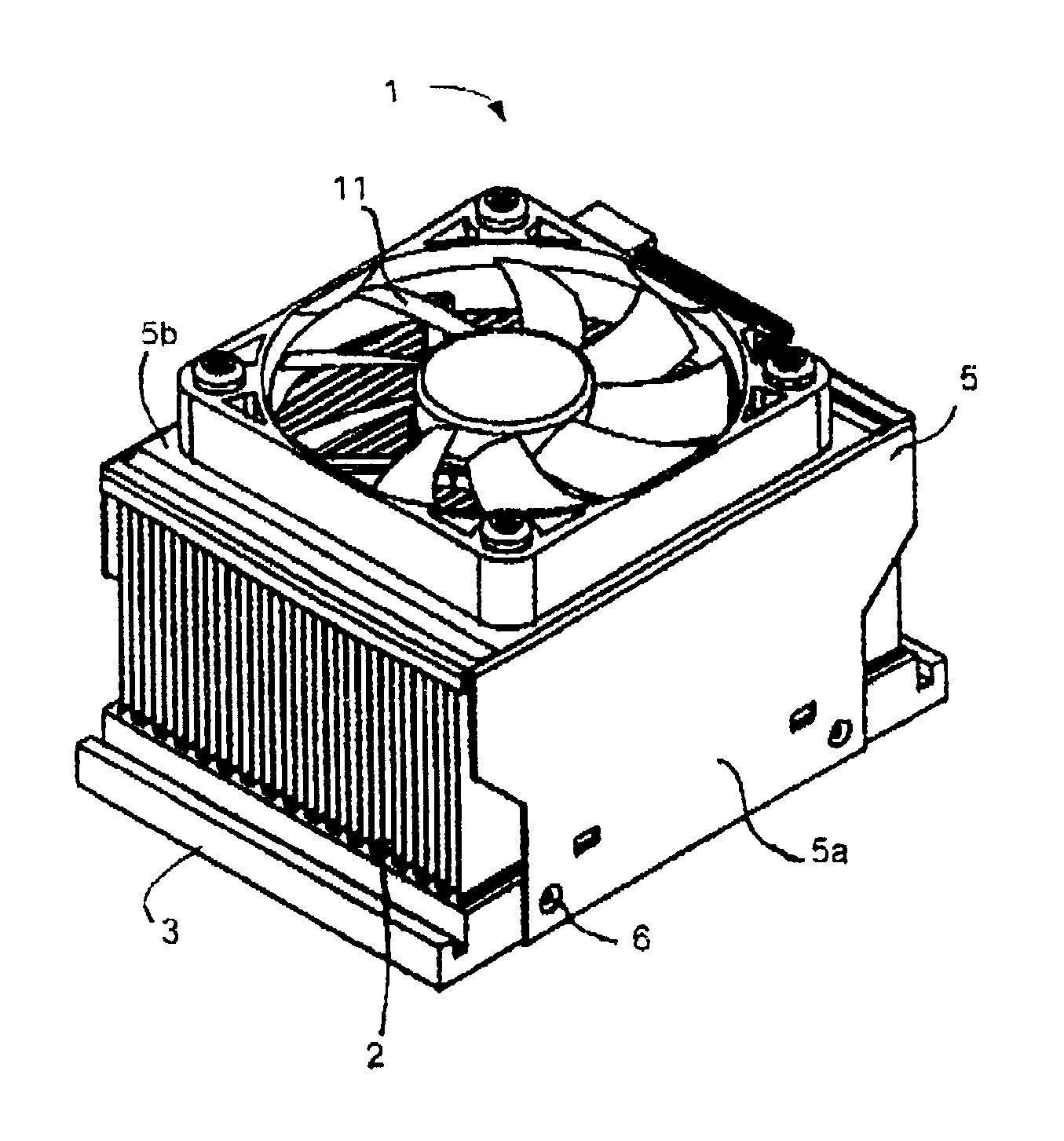
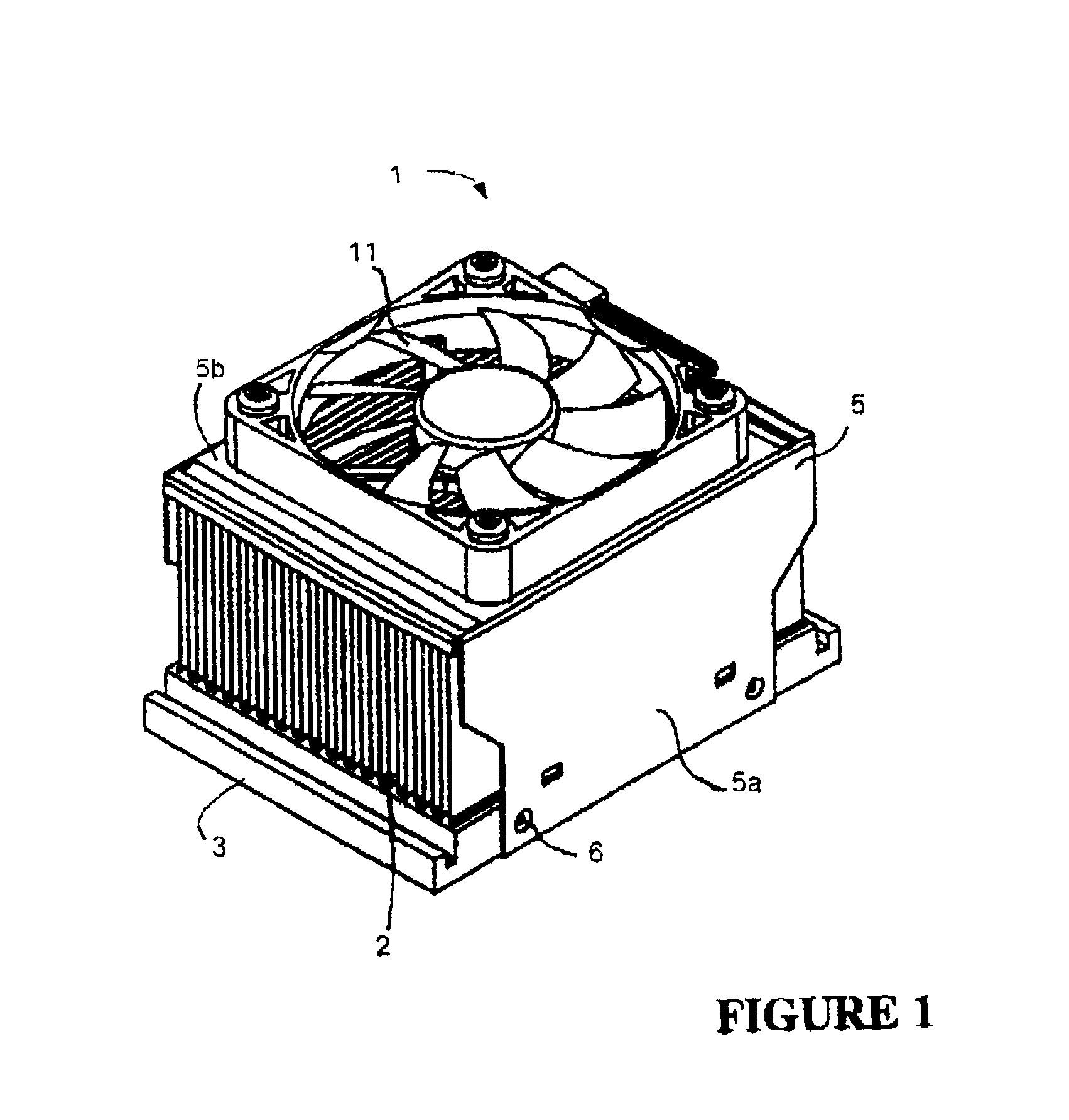
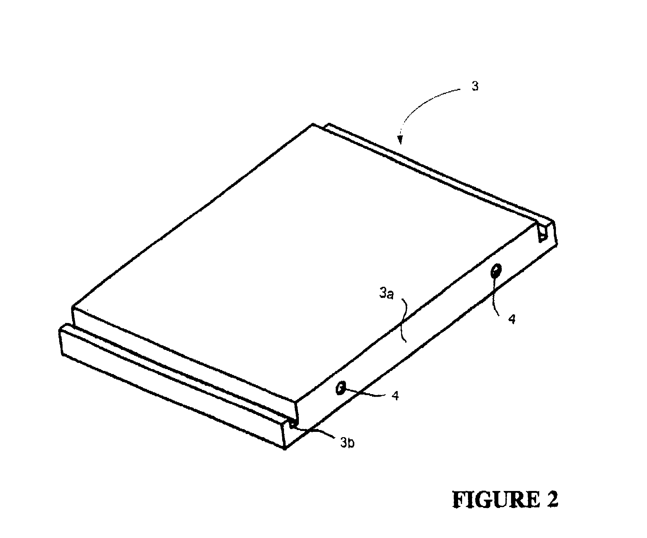
FIG. 1 shows a folded-fin heat sink assembly 1, having folded-fin assembly 2 located on a base plate 3. The folded-fin assembly 2 is secured to the base plate 3 by brazing, soldering or conductive epoxy bonding. A shroud 5, and in some instances a thermally conductive intermediate joining material such as a braze shim, a braze clad, a solder shim or a conductive epoxy, the shroud 5 having side walls 5a and a top wall 5b is located over the folded-fin assembly 2. The shroud is secured to the base plate 3 by means of inwardly locking dimples or projections 6 formed in the shroud side walls (see also FIG. 3), which engage with complementary locking holes 4 formed in the opposed edges 3a of the base plate 3 (see also FIG. 2). An alternate means of joining the shroud and joining material to the base plate may also be through a plurality of laser tack welds along the interface perimeter.

The base plate 3 typically is constructed from copper or aluminum materials and may subsequently be fur...


PUM

PropertyMeasurementUnit
Pressureaaaaaaaaaa
Perimeteraaaaaaaaaa

Abstract

A method of assembling a folded-fin heat sink assembly, the assembly including base plate, a folded fin-assembly and a shroud, includes positioning the folded-fin assembly on a base plate, placing the shroud over the folded-fin assembly, urging the shroud to press the folded-fin assembly against the baze plate and bonding attached to the base plate and a shroud. According to an embodiment, the resulting shroud of the folded-fin assembly acts as extension of the folded-fin heat sink providing additional fin surfaces via which heat can be dissipated.

Description

FIELD OF THE INVENTIONThe present invention relates to a folded-fin heat sink assembly for use as a cooling solution in micro-electronics and / or telecommunication applications. In particular, the present invention relates to a cost effective method of fabrication of a folded-fin heat sink assembly in which a series of heat sink components comprising the assembly may be fixtured in order to facilitate a low cost post processing joining operation, such as brazing, soldering or thermally conductive epoxy bonding.BACKGROUND OF THE INVENTIONIntegrated circuit devices are increasingly being used in modern electronic applications such as computers. During normal operation, integrated circuit devices generate significant amounts of heat. If this heat is not continuously removed, the device may overheat resulting in damage to the device and / or a reduction in operating performance. As a general rule, the performance of integrated circuit devices is likely to improve when they are operated at ...

Claims


Application Information

Patent Timeline
IPC IPC(8): H01L21/02H01L23/467H01L23/367H01L21/48H01L23/34
CPCH01L21/4882H01L23/367H01L23/467H01L23/3672Y10T29/4935H01L2924/0002Y10T29/49826H01L2924/00
Inventor SAS, ADRIAN PIETERO'NEIL, KEVINBAMSEY, ROBERT
Owner TYCO ELECTRONICS CANADA
Why Eureka
Try Eureka