
Tunable external cavity laser

a laser and external cavity technology, applied in semiconductor lasers, instruments, optical elements, etc., can solve the problems of large optical power, small channel separation, and distribution of (wavelength) channel centers, and achieve the effects of avoiding multi-mode lasing, simple design, and simple implementation

Inactive Publication Date: 2005-02-08
INTEL CORP
View PDF148 Cites 111 Cited by
  • Summary
  • Abstract
  • Description
  • Claims
  • Application Information

AI Technical Summary

Benefits of technology

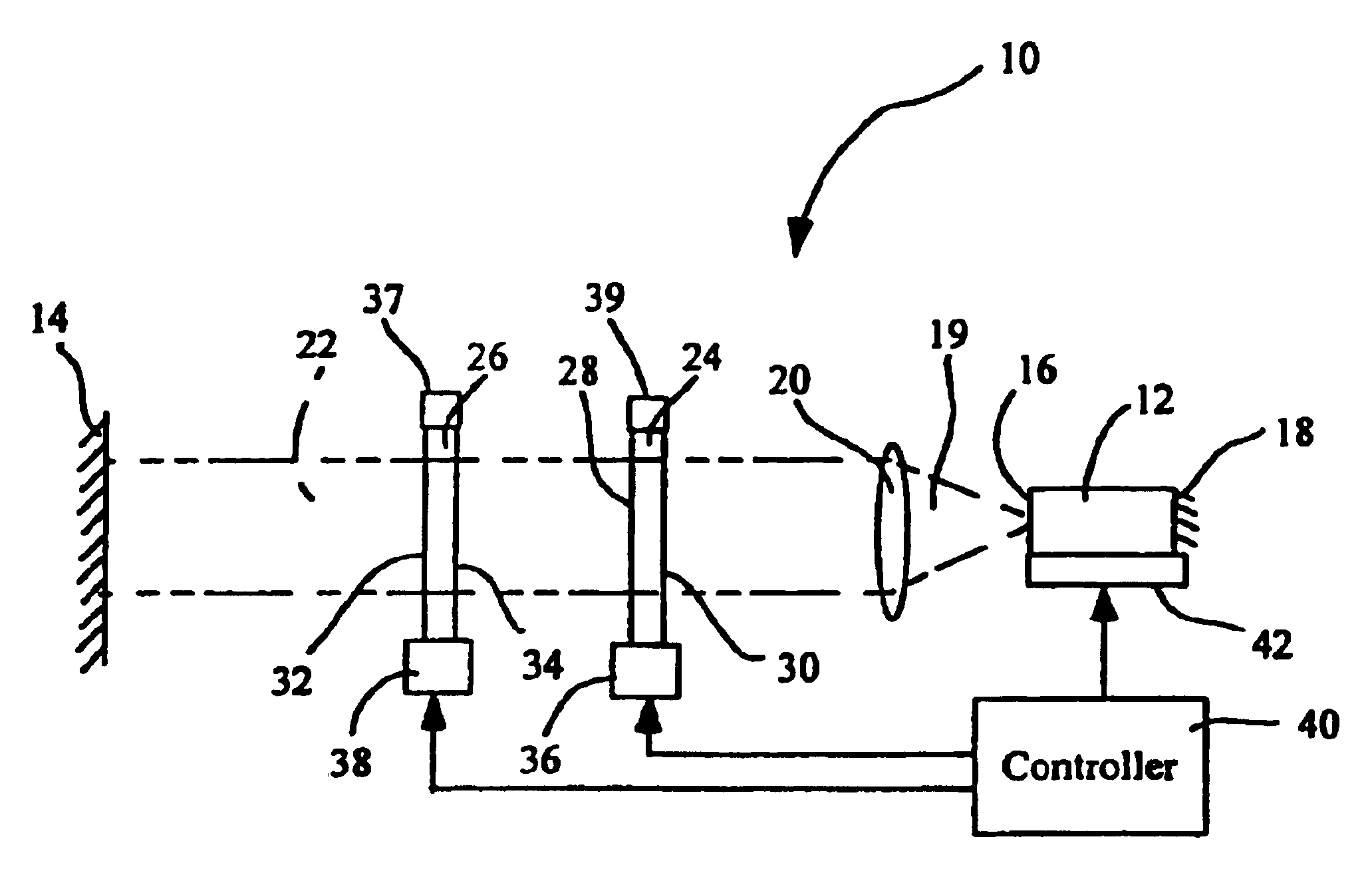
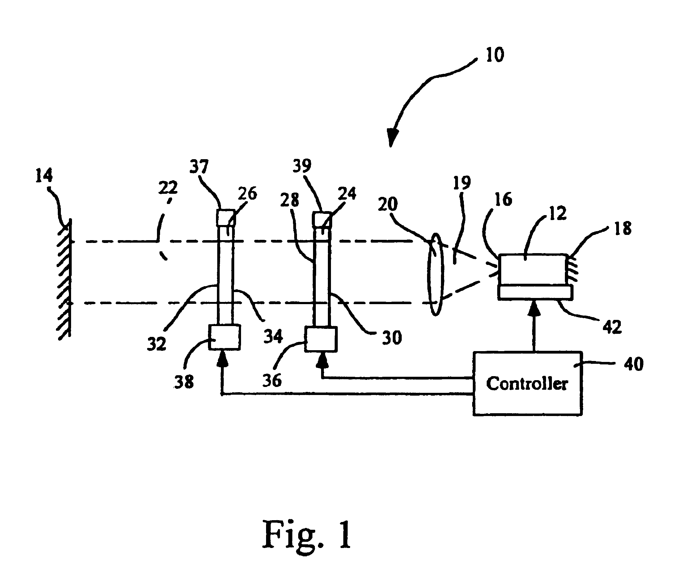
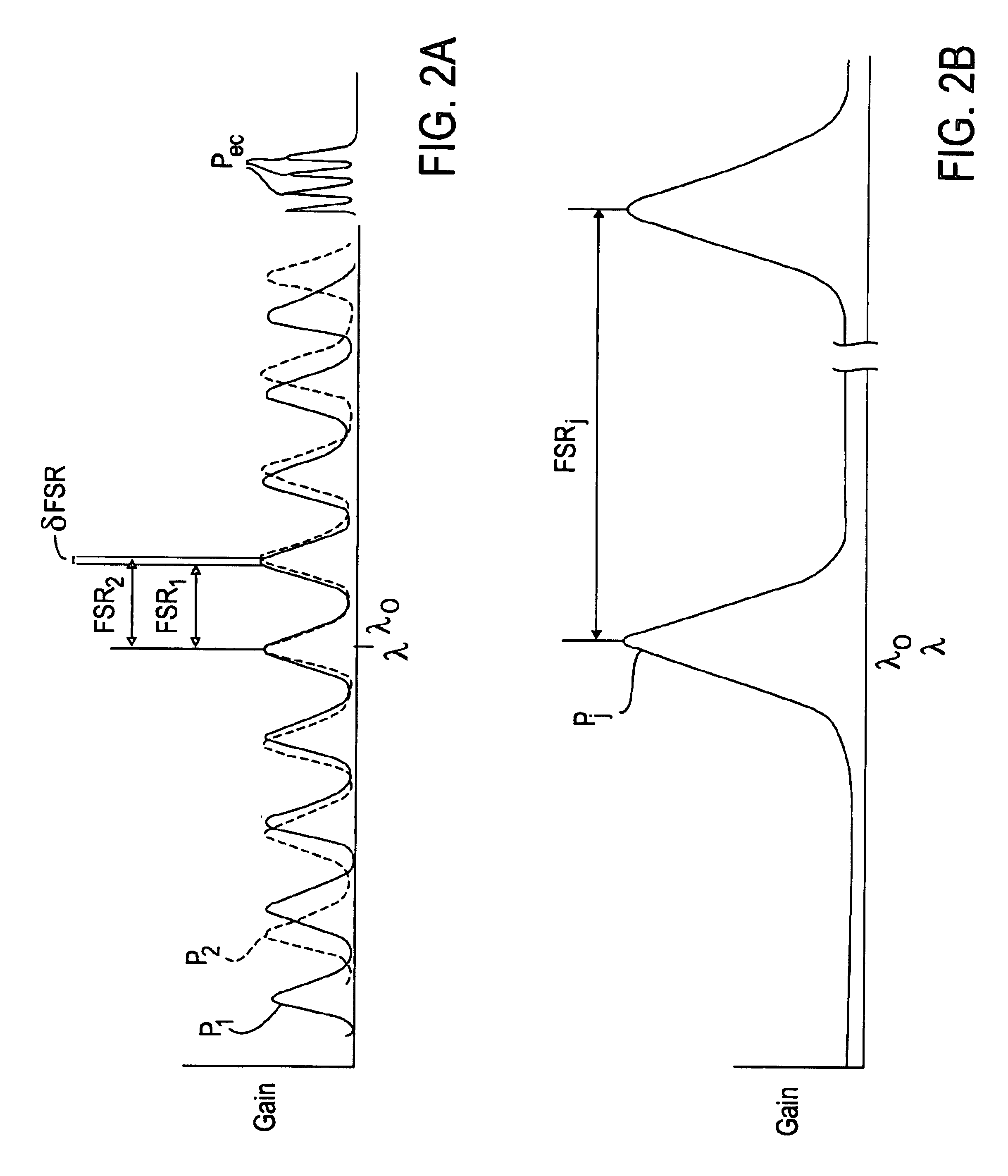
In operation of an external cavity laser using dual tunable etalons in accordance with the invention, the light beam emitted by the gain medium passes through the dual tunable etalons, reflects off the end reflector and returns through the etalons to the gain medium. The free spectral range of each etalon provides a different set of transmission peaks such that only one overlap or alignment of transmission peaks from the two etalons occurs over a selected wavelength range, such as the gain bandwidth of the gain medium. This provides for selection of only one wavelength in the wavelength range and avoids multimode lasing by the external cavity laser. By selective variation of the temperature of the two etalons, the free spectral range of each etalon is varied via thermo-optic effect to allow control of the transmission peaks of the etalons that are aligned, and hence selection of the external cavity laser output wavelength. The finesse of the etalons and the difference between the free spectral ranges of the etalons is selected to prevent multimode lasing at adjacent transmission peaks associated with the etalons. The full width half maximum of the dual etalons is selected to prevent lasing at external cavity modes that are adjacent to the selected wavelength.
The invention provides a tuning system for external cavity lasers and other optical devices that is straightforward to implement, that is simple in design, and which provides fast, effective tuning at selected wavelengths over a wide wavelength range. The use of dual tunable elements that are both tuned to provide wavelength selection allows use of a shorter external laser cavity and effective side mode suppression, and provides a tuning mechanism for external cavity lasers that can be easily adapted or re-configured for different DWDM network requirements. These and other objects and advantages of the invention will be apparent from the detailed description below.

Problems solved by technology

Greater bandwidth requirements will likely result in smaller channel separation in the future.
Unfortunately, statistical variation associated with the manufacture of individual DFB lasers results in a distribution of (wavelength) channel centers.
Variations in DFB operating temperature permit a range of operating wavelengths enabling servo control; however, conflicting demands for high optical power, long lifetime, and low electrical power dissipation have prevented use in applications that require more than a single channel or a small number of adjacent channels.
Achieving these goals typically has resulted in increased, size, cost, complexity and sensitivity in tunable external cavity lasers.

Method used


Image

  • Tunable external cavity laser
  • Tunable external cavity laser
  • Tunable external cavity laser

Examples


Embodiment Construction

Referring more specifically to the drawings, for illustrative purposes the present invention is embodied in the apparatus shown in FIG. 1 through FIG. 17. It will be appreciated that the apparatus may vary as to configuration and as to details of the parts, and that the method may vary as to details and the order of the acts, without departing from the basic concepts as disclosed herein. The invention is disclosed primarily in terms of use with an external cavity laser. The invention, however, may be used with various types of laser devices and optical systems. It should also be understood that the terminology used herein is for the purpose of describing particular embodiments only, and is not intended to be limiting, since the scope of the present invention will be limited only by the appended claims. The relative sizes of components and distances therebetween as shown in the drawings are in many instances exaggerated for reason of clarity, and should not be considered limiting.

Ref...


PUM


Abstract

Apparatus and methods that utilize tunable elements to provide for selective wavelength tuning of a light beam. The apparatus comprises a first tunable wavelength selection element having a first adjustable free spectral range, a second tunable wavelength selection element having a second adjustable free spectral range, with the first and second tunable wavelength selection elements configured to define a tunable joint transmission peak. The first and second tunable wavelength selection elements respectively define first and second pluralities of tunable transmission peaks, wherein respective ones of each of the first and second plurality of transmission peaks are aligned to obtain a joint transmission peak that may be adjusted by tuning the wavelength selection elements. The free spectral ranges of the wavelength selection elements are configured to enable a Vernier tuning effect.

Description

BACKGROUND OF THE INVENTIONThe demand for increased bandwidth in fiberoptic telecommunications has driven the development of sophisticated transmitter lasers usable for dense wavelength division multiplexing (DWDM) systems wherein multiple separate data streams propagate concurrently in a single optical fiber. Each data stream is created by the modulated output of a semiconductor laser at a specific channel frequency or wavelength, and the multiple modulated outputs are combined onto the single fiber. The International Telecommunications Union (ITU) presently requires channel separations of approximately 0.4 nanometers, or about 50 GHz, which allows up to 128 channels to be carried by a single fiber within the bandwidth range of currently available fibers and fiber amplifiers. Greater bandwidth requirements will likely result in smaller channel separation in the future.Telecom DWDM systems have largely been based on distributed feedback (DFB) lasers. DFB lasers are stabilized by a w...

Claims


Application Information

Patent Timeline
Patent Type & Authority Patents(United States)
IPC IPC(8): G02B26/00G02B5/28G02B6/34G02B7/00H01S5/00H01S5/14H04J14/02H01S5/0687H01S5/022
CPCG02B5/281G02B5/284G02B26/001G02B26/06H01S5/141H04J14/02H01S5/02248H01S5/0687H01S3/1062H01S5/02325
Inventor MCDONALD, MARK E.DAIBER, ANDREWCHAPMAN, WILLIAM B.MALUF, NADIM
Owner INTEL CORP
Learn More