
Regeneration of particulate filter

a technology of particulate filter and filter bed, which is applied in the direction of mechanical equipment, machines/engines, electric control, etc., can solve the problems of excessive rise in the temperature of the filter bed at the combustion stage of particulate matter, large amount of time required for the filter temperature to rise, etc., to prevent the effect of deterioration of the filter

Inactive Publication Date: 2005-02-08
NISSAN MOTOR CO LTD
View PDF9 Cites 117 Cited by
  • Summary
  • Abstract
  • Description
  • Claims
  • Application Information

AI Technical Summary

Benefits of technology

In filter regeneration, it is preferable to reduce the period of filter temperature increase in order to economize on the fuel which is consumed during the temperature increase period. It is also necessary to appropriately control the combustion rate following the beginning of particulate matter combustion in order to prevent deterioration of the filter caused by excessive rises in the temperature of the filter bed due to particulate matter combustion.
It is therefore an object of this invention to shorten the amount of time required to raise the filter temperature while suppressing temperature increase in the filter bed caused by particulate matter combustion.
It is therefore a further object of this invention to prevent the residual particulate matter from remaining in the filter upon the completion of filter regeneration.

Problems solved by technology

In regeneration devices according to the prior art, increases in the filter temperature become faster when attempts are made to shorten the temperature increase period, and thus the temperature of the filter bed rises excessively at the particulate matter combustion stage.
On the other hand, if attempts are made to suppress temperature increase in the filter bed at the particulate matter combustion stage, a large amount of time is required for the filter temperature to rise.
Further, if a part of the particulate matter remains in the filter upon completion of regeneration processing, pressure loss in the filter increases, causing an increase in fuel consumption during subsequent engine operations.
Moreover, the residual particulate matter in the filter causes bias in the distribution of particulate matter trapped by the filter when the filter subsequently traps particulate matter.
This bias leads to bias in the combustion temperature during subsequent filter regeneration processing, thereby causing damage to the durability of the filter.

Method used


Image

  • Regeneration of particulate filter
  • Regeneration of particulate filter
  • Regeneration of particulate filter

Examples


second embodiment

Next, referring to FIGS. 13A and 13B, this invention related to setting of a target temperature of the filter inlet in the first phase, or in other words pertaining to the processing content of the step S5 in the main routine of FIG. 3, will be described.

first embodiment

In this embodiment, as shown in FIG. 13B, the first phase is divided into a first half and a second half. In the first half, the target temperature of the filter inlet is set to a target value tT2 which is larger than the target value tT1 and in the second half, the target temperature of the filter inlet is reduced from the target value tT2 toward the target bed temperature tTbed.

By setting the target value tT2 for the filter inlet temperature to a larger value than the target value tT1 in the first half, the rate of temperature increase of the bed temperature Tbed rises and the timing of arrival at the target bed temperature tTbed quickens, and thus the time period t1 is shortened to t1A. The target temperature tT2 of the filter inlet is reduced prior to the bed temperature Tbed reaching the target bed temperature tTbed, and hence overshoot in the bed temperature Tbed such as that shown in FIG. 12A does not arise. For comparison, the bed temperature Tbed and the target value tT1 f...


PUM


Abstract

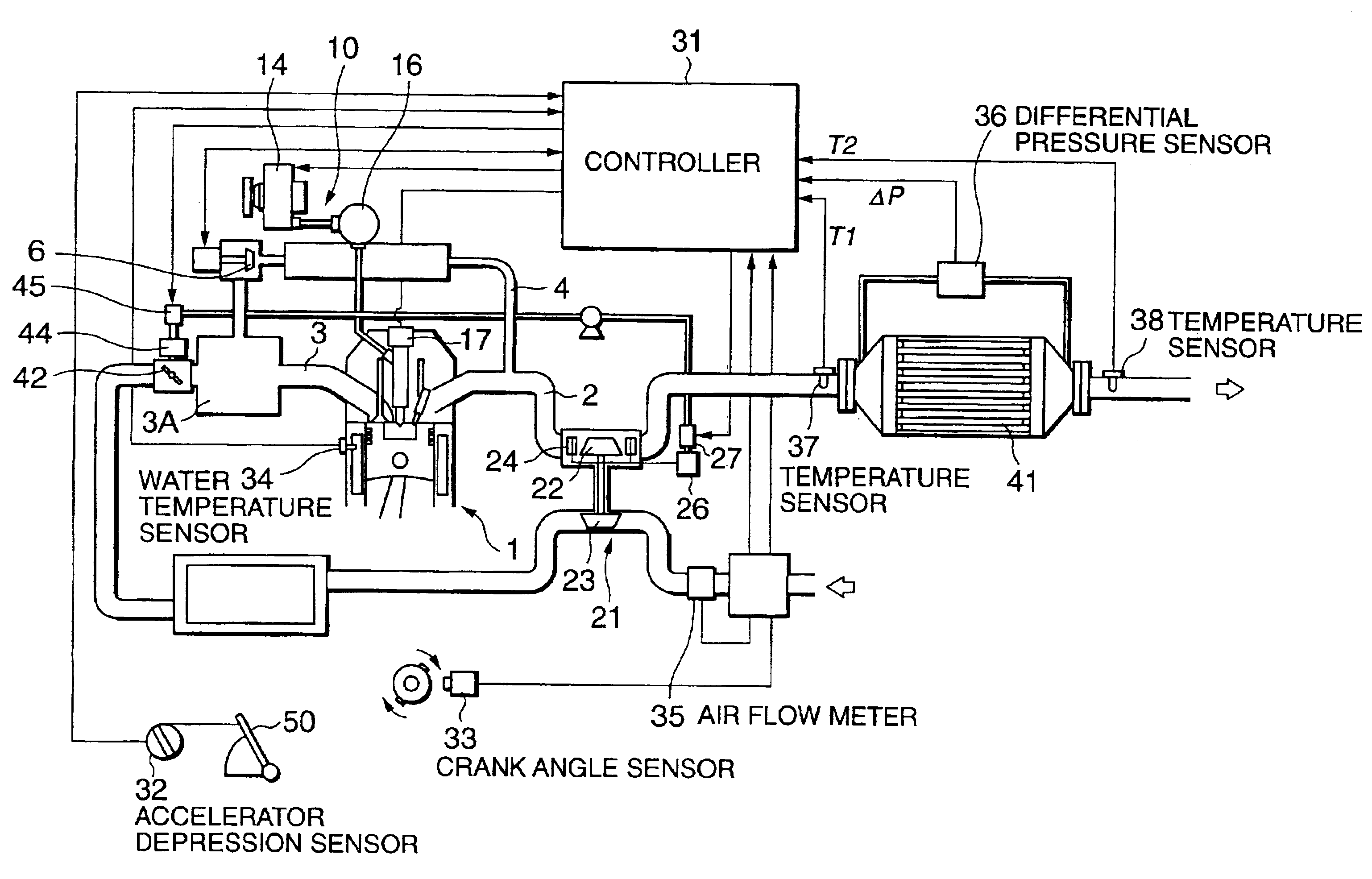
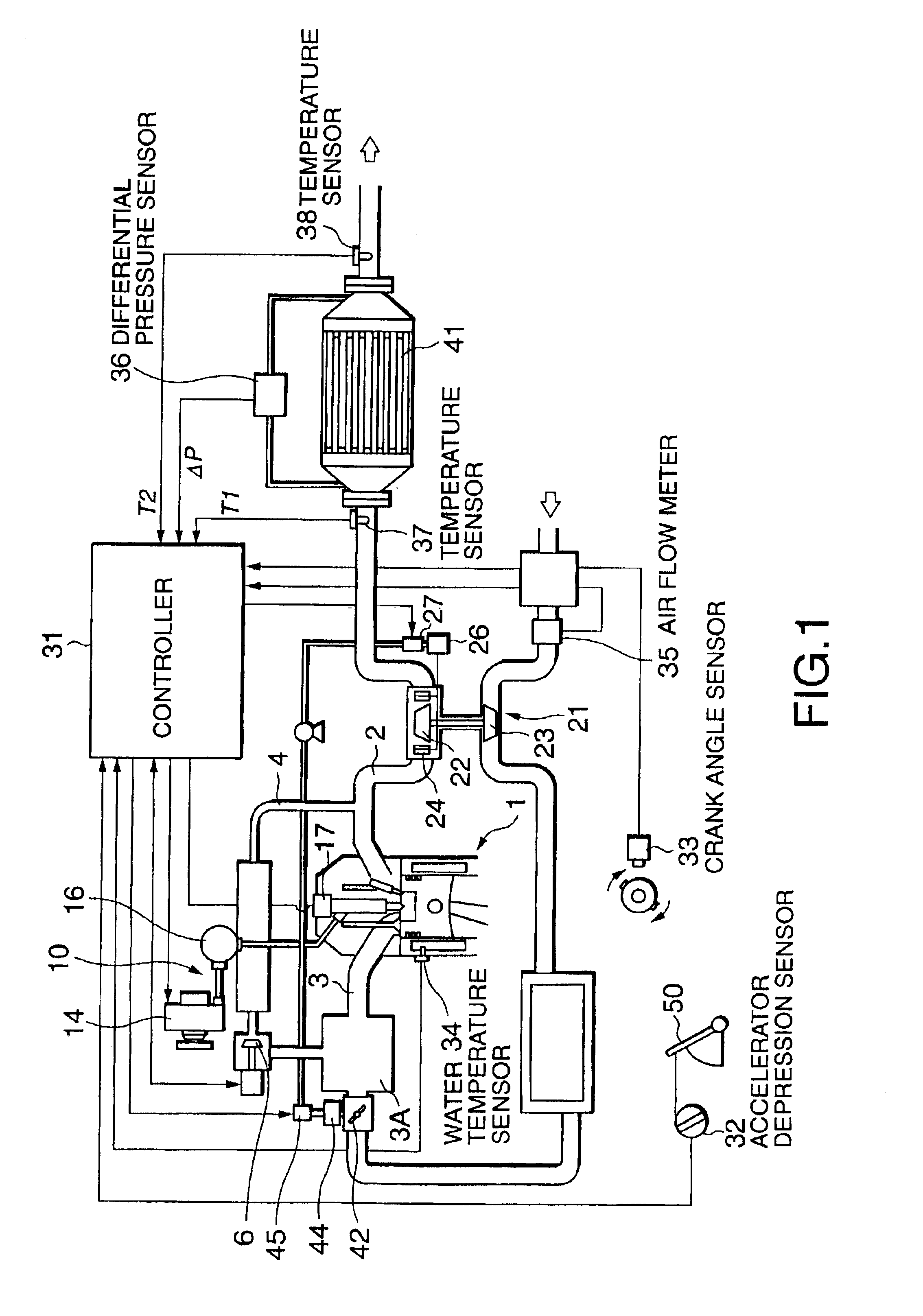
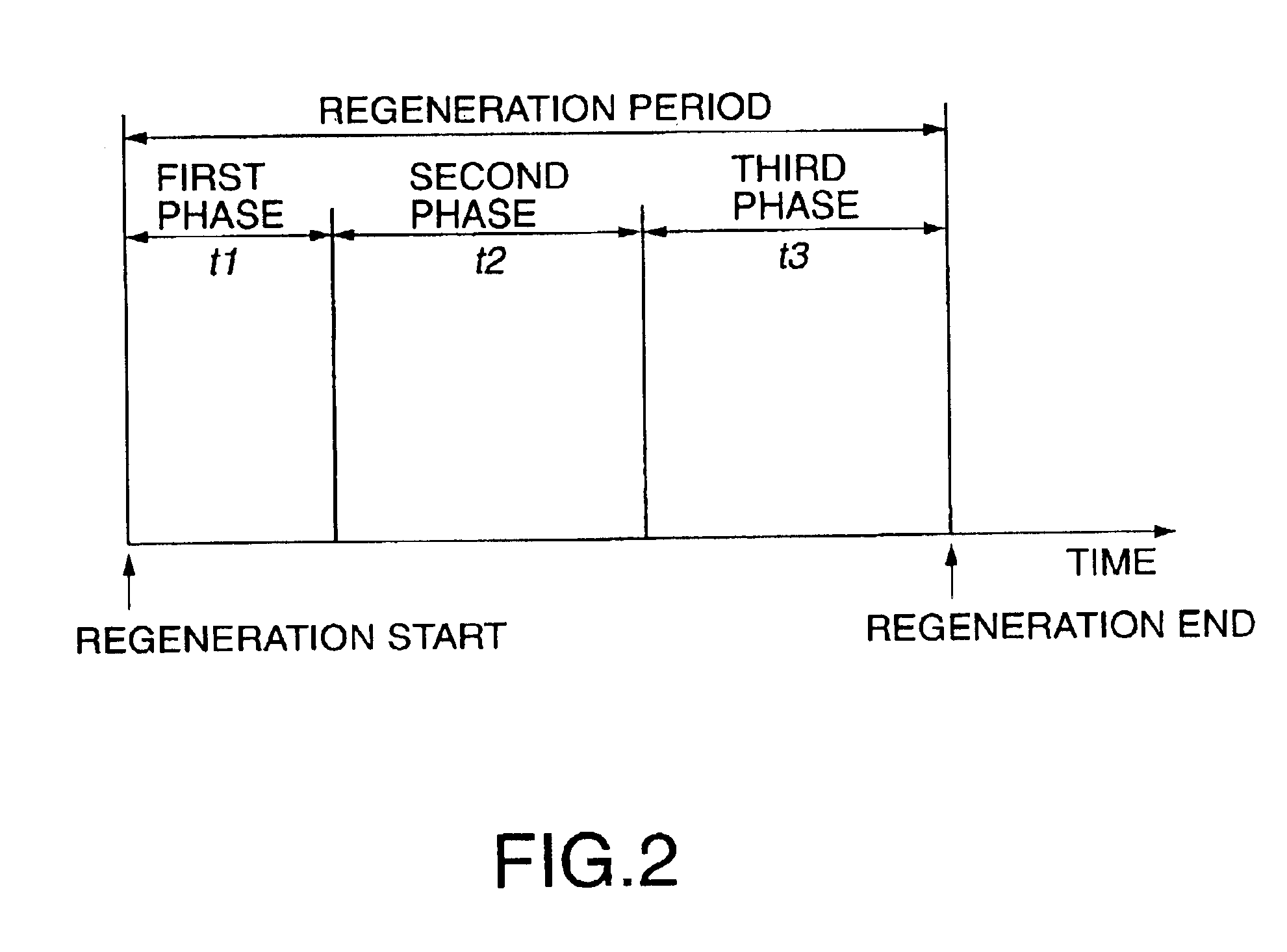
An exhaust passage (2) of a diesel engine (1) is provided with a filter (41) for trapping particulate matter. Regeneration of the filter (41) is divided into first to third phases. In the first phase the filter temperature is raised to the combustion temperature of the particulate matter in a short period of time through control of the exhaust gas temperature. In the second phase, the oxygen concentration of the exhaust gas is held at a predetermined low level while the filter temperature is maintained so as to prevent excessive combustion of particulate matter. In the third phase, wherein the amount of trapped particulate matter has been reduced, the oxygen concentration of the exhaust gas is held at a predetermined high level while the filter temperature is maintained so as to complete the combustion of the trapped particulate matter.

Description

FIELD OF THE INVENTIONThis invention relates to the regeneration of a diesel particulate filter for trapping particulate matter contained in engine exhaust gas.BACKGROUND OF THE INVENTIONJP2000-179326A, published by the Japanese Patent Office in 2000, discloses a regeneration method for a diesel particulate filter (DPF) which traps particulate matter contained in the exhaust gas of a diesel engine. In this method, when the amount of particulate matter trapped in the filter reaches a predetermined amount, the filter temperature is raised to the self-ignition temperature of the particulate matter, whereby the trapped particulate matter is burned and thus the particulate matter is removed from the filter. As a result, the DPF is returned to a state in which particulate matter may be trapped.The filter temperature is raised by raising the exhaust gas temperature, which is performed by controlling the fuel injection amount and injection timing of the engine. When the temperature of the f...

Claims


Application Information

Patent Timeline
Patent Type & Authority Patents(United States)
IPC IPC(8): F02D41/02F01N3/02F02B37/00F02B37/22F02D21/08F02D23/00F02D41/04F02D41/38F02M25/07
CPCF01N3/023F02D41/0245F02D41/029F02D41/025F01N2560/08F02B37/22Y02T10/26F02D41/1446F02D41/1454Y02T10/12
Inventor KAWASHIMA, JUNICHITSUTSUMOTO, NAOYATABATA, MUNEHIROOTAKE, MAKOTO
Owner NISSAN MOTOR CO LTD
Learn More