Hydrotherapy jet with rotating outlet

a technology of jets and outlet valves, applied in the field of hydrotherapy jets, can solve the problems of increasing the cost and complexity of the design and manufacture of jets, adding complexity in the design and manufacturing of jets, and requiring a bridge, so as to achieve less complex, less expensive, and more durable

Inactive Publication Date: 2005-02-01
WATERWAY PLASTICS
View PDF19 Cites 27 Cited by
  • Summary
  • Abstract
  • Description
  • Claims
  • Application Information

AI Technical Summary

Benefits of technology

The present invention seeks to provide a hydrotherapy jet with an improved mechanism to allow the jet's outlet to rotate, the mechanism being less complex, less expensive and more durable. The invention also seeks to provide a hydrotherapy jet having outlets that rotate without relying on bearings while at the same time avoiding structures that interfere with the flow of water through the inlet and from the outlets.

Problems solved by technology

One disadvantage of these rotating jets is that they rely on internal bearings to allow the outlet or eyeball to rotate.
This approach is effective in allowing free rotation, but the bearings are relatively expensive and add complexity in design and manufacturing of the jets.
One disadvantage of this arrangement is that the bridge adds to the cost and complexity of the jet's design and manufacture.
However, the vacuum effect of the venturi tends to pull the outlet toward the back of the jet.
As a result, the pin / bushing combination must hold the eyeball within the cup against the pull of the venturi vacuum, which makes the bridge type jet even more difficult to design and manufacture.
Also, the bridge interferes with the stream of the water from the rotating outlet as it passes under the arms of the bridge.
This results in multiple interruptions in the flow of water, which may be undesirable in some circumstances.
On disadvantage of this jet arrangement is that if the rear of the jet is used as the water inlet, a significant portion of the inlet is blocked by a rear axial surface that supports the circular opening.
This restricts the amount of water that can pass into the jet and creates turbulence in the water that does pass.

Method used


Image

  • Hydrotherapy jet with rotating outlet
  • Hydrotherapy jet with rotating outlet
  • Hydrotherapy jet with rotating outlet

Examples


Embodiment Construction

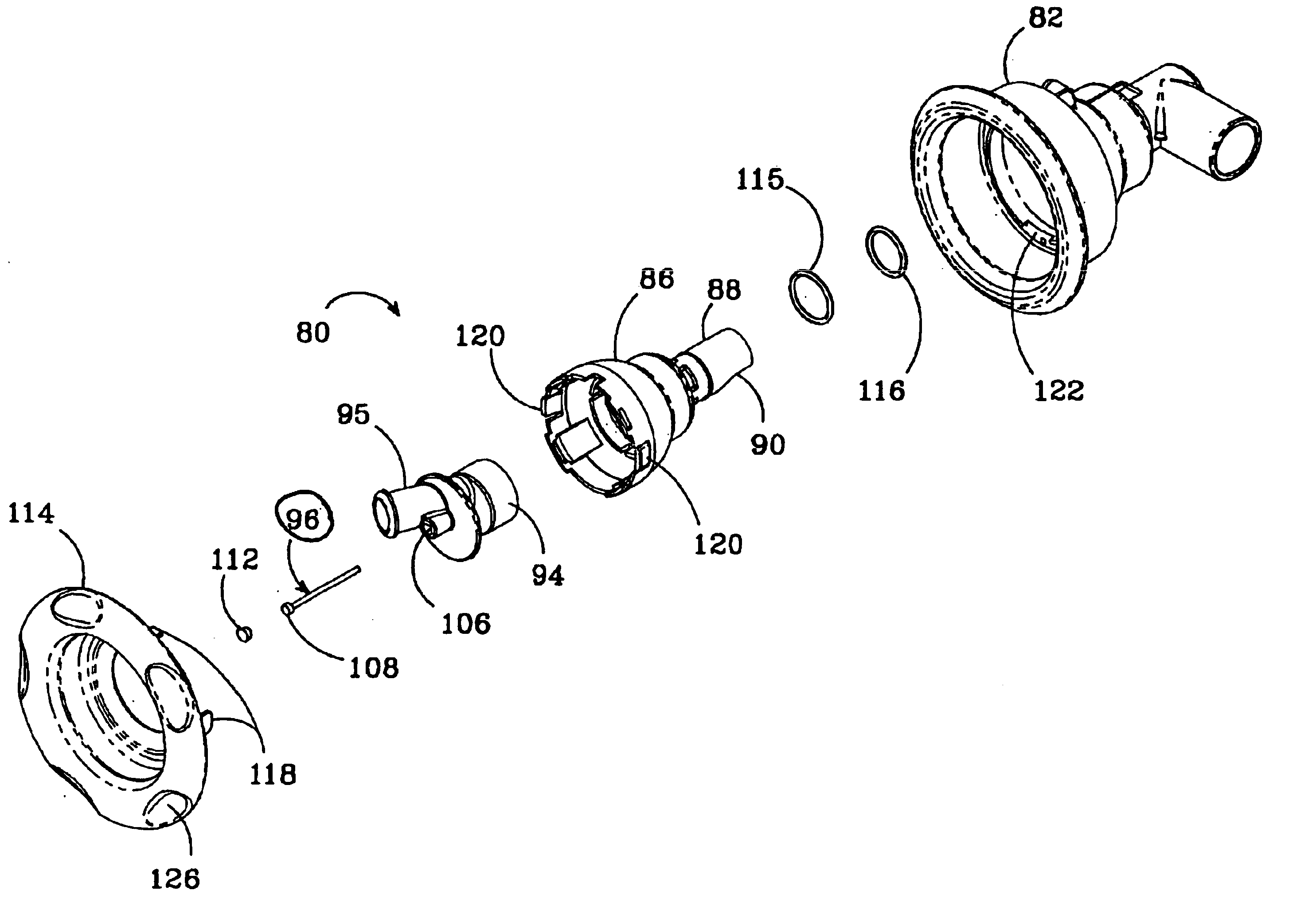
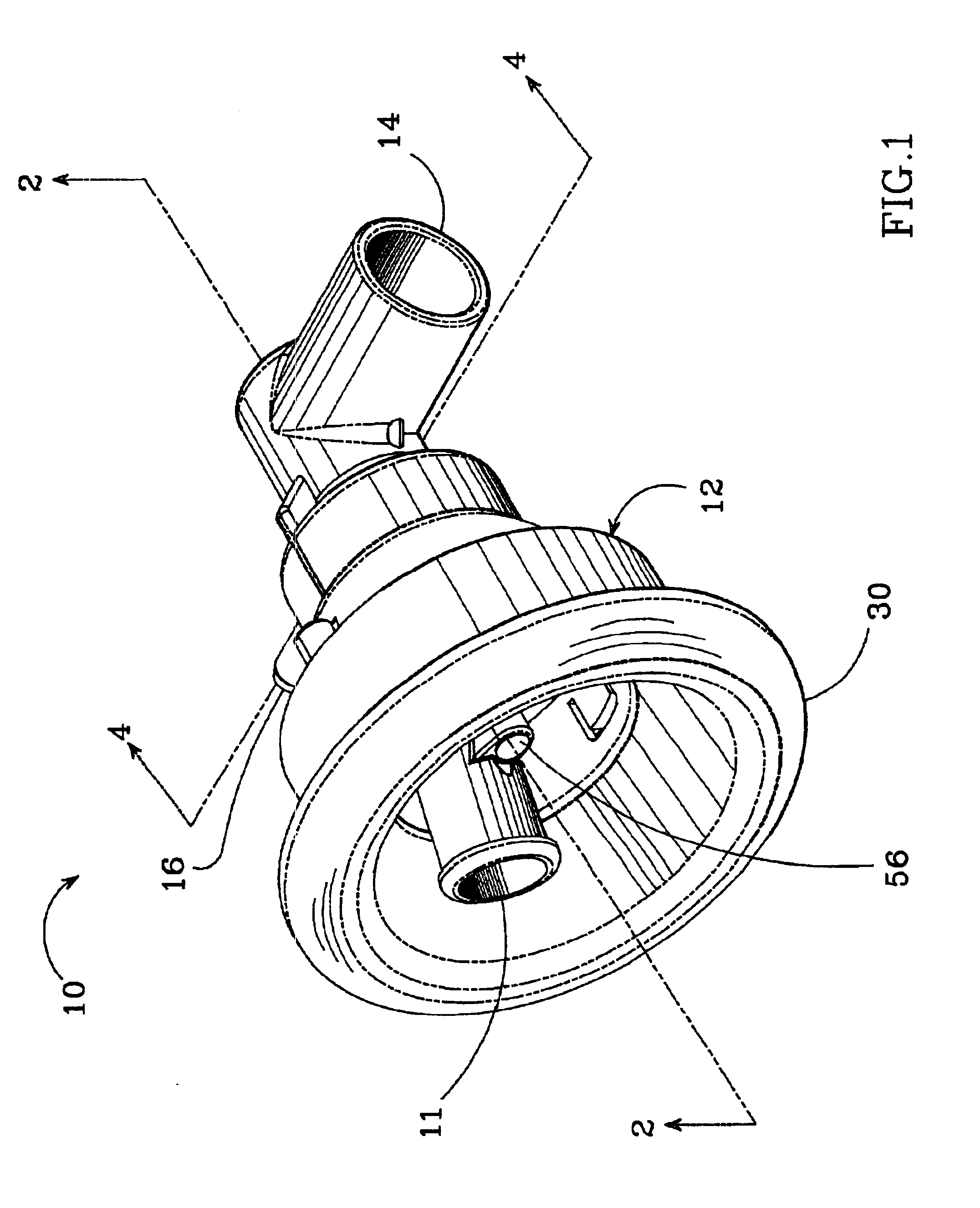
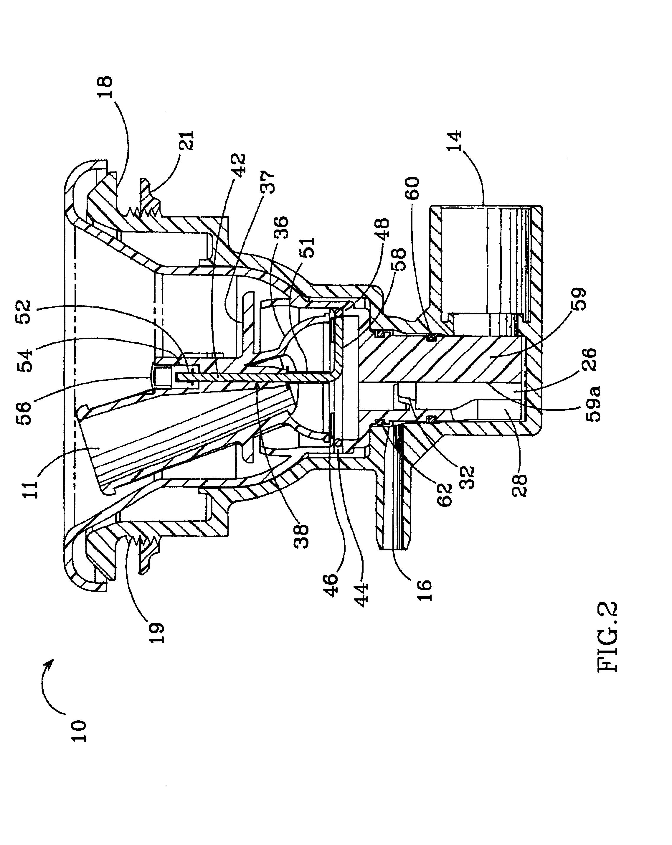
FIGS. 1-3 show one embodiment of a hydrotherapy jet 10 constructed in accordance with the present invention, having a rotating outlet 11. The jet 10 and its components are preferably formed from a water impervious plastic such as ABS, PVC or CPVC. It is particularly adapted to be positioned below the water level on the spa or tub wall, with the majority of the jet positioned behind the spa's water contacting wall.

The jet 10 includes a jet body 12 having a water inlet 14 that receives a standard water supply tube. The body 12 can also have an air inlet tube 16 to allow air into the body 12 in applications where aerated water is desired. The jet body 12 has an external flange 18 that is positioned on the spa's water contacting wall. The outside surface of the body 12, adjacent to the flange 18, has a threaded section 19 for mating with the threads of a wall fitting 21. A circular gasket or other devices or compounds that provide a watertight seal (not shown) can be on the wall fitting...


PUM


Abstract

A hydrotherapy jet is disclosed which has a jet body with a water inlet to allow water to flow into it. An eyeball with one or more outlets is mounted to the body to allow water to flow out of the body through the outlets. The flow of water through the outlets causes the eyeball to rotate. A retaining pin is mounted within the jet body to hold the eyeball to the body, with the eyeball rotating around said pin. A system for providing a hydrotherapy jet to reservoir of water is also disclosed and includes a reservoir shell capable of holding water with a plurality of hydrotherapy jets according to the invention that are mounted around the reservoir shell. A water pump system circulates water from the reservoir to said jets.

Description

BACKGROUND OF THE INVENTION1. Field of the InventionThis invention relates to hydrotherapy jets.2. Description of the Related ArtVarious hydrotherapy jets have been developed for use in spas, hot tubs, pools and bath tubs that discharge a stream of water, which can be aerated through a variety of discharge nozzles. The designs provide different flow characteristics that result in different massage affects being experienced by the body. Such jets have been found to produce a pleasing massaging effect for many users, and have become quite popular. In the design of single or multi-user spas or tubs, it is common to use a variety of different jet nozzles to provide a variety of different massaging effects.Early jets simply discharged a steam of warm water along the longitudinal axis of the jet body, with later jets providing aeration of the water stream. Since then, numerous jets have been developed in which the direction of the stream can be adjusted. For example, U.S. Pat. No. 5,269,0...

Claims


Application Information

Patent Timeline
Patent Type & Authority Patents(United States)
IPC IPC(8): B05B3/02B05B3/06A61H33/00
CPCA61H33/6063B05B3/06A61H2201/1238
Inventor HOLTSNIDER, MICHAEL D.
Owner WATERWAY PLASTICS
Why Eureka
Try Eureka