Method for stacking surface structured optical films
a structure and optical film technology, applied in the field of optical displays, can solve the problems of increasing the chance of damage to the film when removing the protective liners, the time required to remove the protective liners, so as to reduce the chance of damage to the film, reduce the number of steps required, and facilitate the handling of the film
- Summary
- Abstract
- Description
- Claims
- Application Information
AI Technical Summary
Benefits of technology
Problems solved by technology
Method used
Image
Examples
example 1
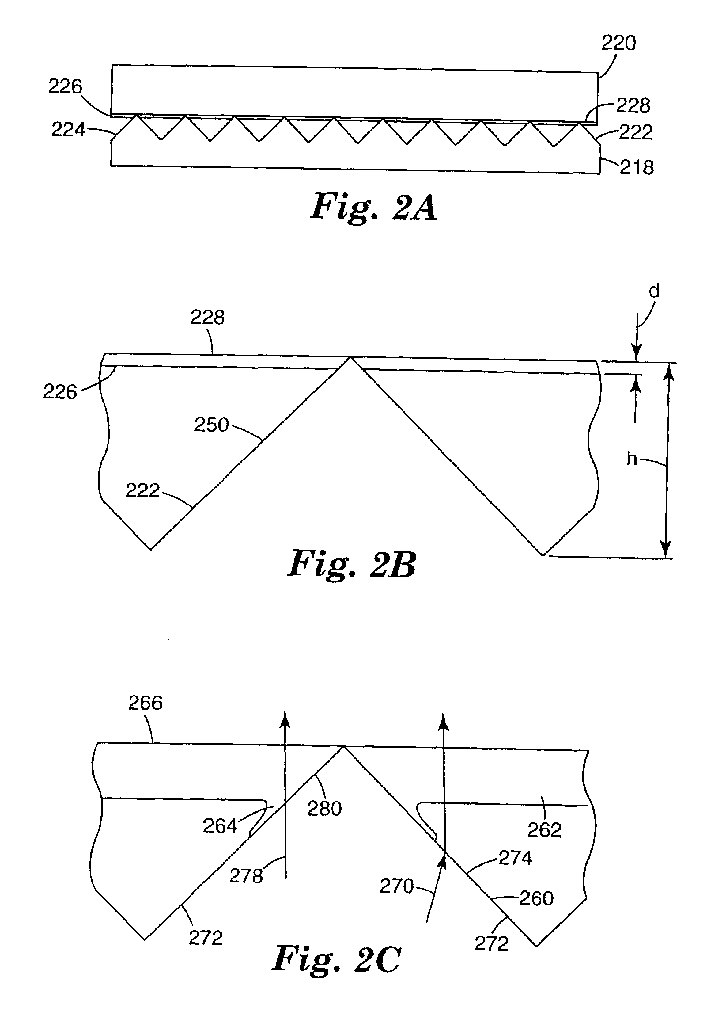
Samples of the construction illustrated in FIG. 2A were made using a prismatically structured film that had a 50 μm thick substrate with prismatic structures 12 μm in height. The apex angle of the prismatic features was about 90°. The samples were made by applying a thin coating of adhesive to the planar side of a sheet of 3M Thin Brightness Enhancement Film (TBEF). A second sheet of TBEF was laminated to the adhesive with the prismatic grooves oriented approximately 90° to the grooves of the first sheet.
Cross-sections through the structures, taken using a scanning electron microscope (SEM), are illustrated in FIGS. 3 and 4 for two sets of laminates formed using different adhesives. The adhesive used for the construction shown in FIG. 3 was a layer, approximately 1 μm thick, of iso-octyl acrylate / acrylic acid (IOA / AA) in the ratio of 81% / 19%, crosslinked at 0.15% Bisamide to adhesive solids. The adhesive used for the construction shown in FIG. 4 was a layer of UV curable urethane wi...
example 2
Several laminated constructions of crossed TBEF film were formed using different types of adhesives, over a variety of layer thickness. The brightness of light passing through the constructions was measured and normalized against a pair of crossed TBEF films that had no adhesive: the results are presented in FIG. 5. Optical brightness of the laminate constructions was measured using an Autronic Conoscope which measures the brightness distribution versus angle that passes through the film.
Five different types of adhesives were used in the experiments. Curve 502 corresponds to a layer of urethane acrylate (UA) and iso-octyl acrylate (IOA) acrylic acid (AA) having a first level of cross-linking. Curves 504 and 506 correspond also to urethane acrylate, at respectively increased levels of cross-linking of the IOAAA component. Curve 508 corresponds to a layer of iso-octyl acrylate / acrylic acid (IOA / AA) and curve 510 corresponds to a layer of epoxy acrylate (EA) and IOA / MA / AA without cross...
example 3
The environmental stability of the laminated construction was tested by exposing samples of the laminated construction fabricated using IOA / AA and a blend of IOAAA or IOA / MA / AA and UV curable epoxies or urethanes to temperatures of 100° C., 85° C., and 65° C. at a relative humidity of 95% for 1 week. All the samples passed visual inspection, and there were no failures due to separation or bubbling. This is due to the ability of gasses to move in and out of the laminate very easily. All samples did curl to a certain degree. Curling is thought to occur because of the difference in expansion coefficients between down and cross web directions. The curl remains in the sample because the adhesive can shift in the heated environment. The curling may be reduced by using adhesives having a higher glass transition temperature, by crosslinking to a higher degree, or by matching the expansion coefficients. Curl is not an issue for assemblies, where the film layers are held flat in the display.
T...
PUM
 Abstract
Description
Claims
Application Information
 - R&D
- Intellectual Property
- Life Sciences
- Materials
- Tech Scout
- Unparalleled Data Quality
- Higher Quality Content
- 60% Fewer Hallucinations
Browse by: Latest US Patents, China's latest patents, Technical Efficacy Thesaurus, Application Domain, Technology Topic, Popular Technical Reports.
© 2025 PatSnap. All rights reserved.Legal|Privacy policy|Modern Slavery Act Transparency Statement|Sitemap|About US| Contact US: help@patsnap.com


