
VCDL with linear delay characteristics and differential duty-cycle correction

Inactive Publication Date: 2005-01-18
INFINEON TECH AG
View PDF7 Cites 37 Cited by
  • Summary
  • Abstract
  • Description
  • Claims
  • Application Information

AI Technical Summary

Benefits of technology

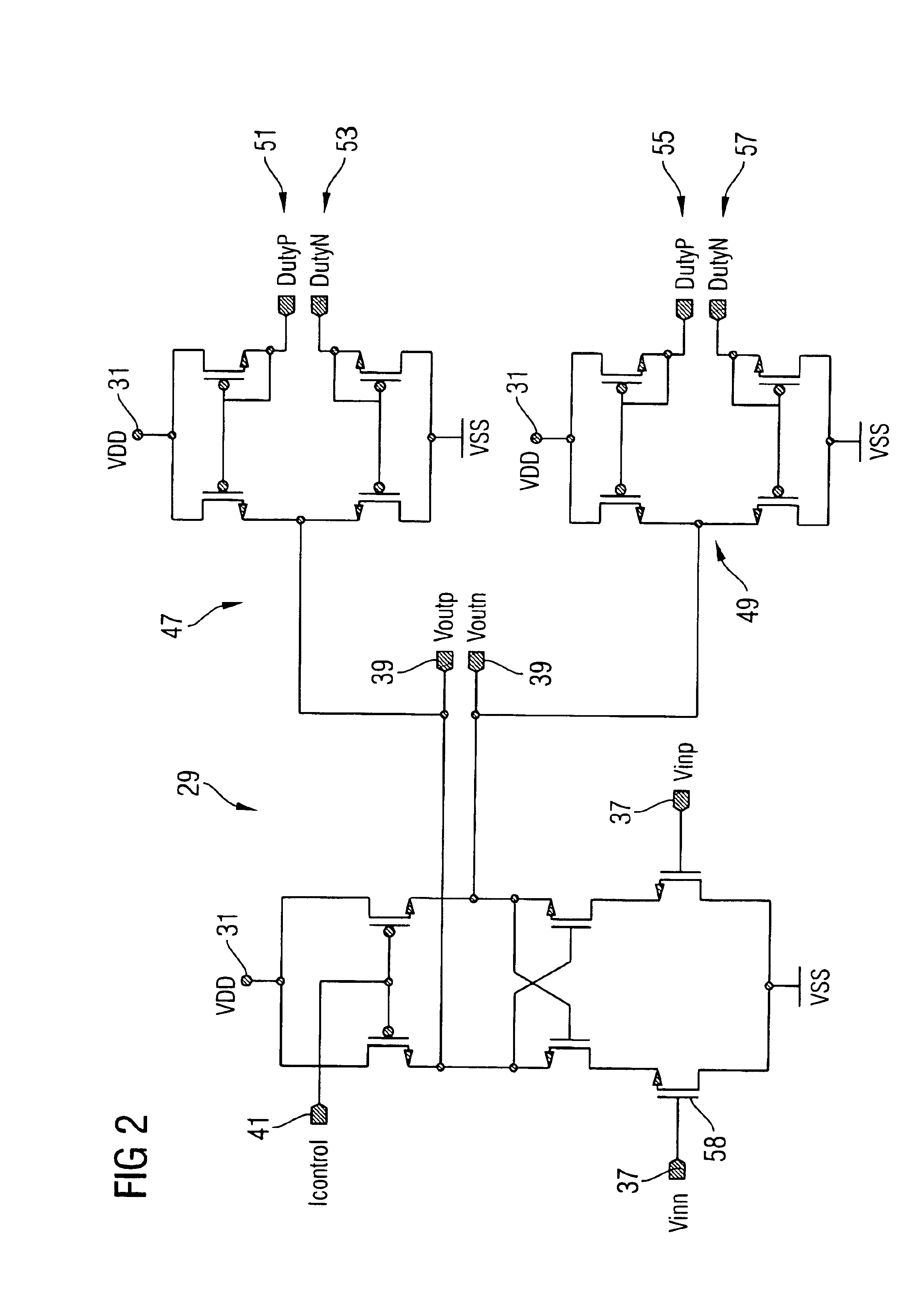
The present invention provides a VCDL with a relatively linear delay characteristic over the full range of the control voltage by forming the VCDL from a voltage-to-current converter in combination with a CCDL (Current Controlled Delay Line). In addition, the duty cycle correction of the resulting VCDL is improved using another voltage-to-current converter.
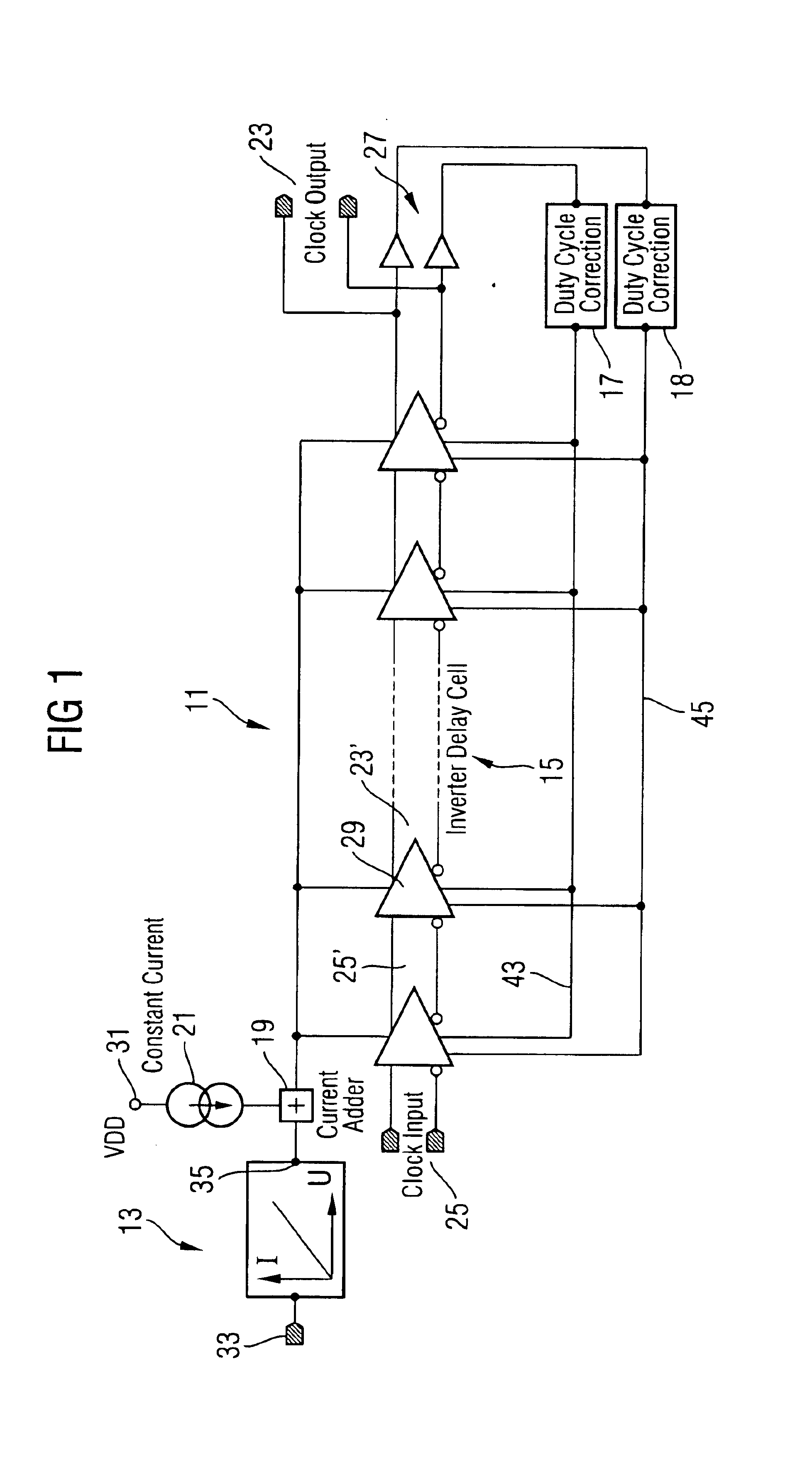
In general terms, the present invention is a voltage-controlled delay line comprising a series of delay cells outputting a clock output signal having a delay relative to a clock input signal input to the series of delay cells. A duty-cycle correction section corrects the duty cycle of the clock output signal by providing opposite current outputs which are fed back to the series of delay cells to substantially simultaneously charge and discharge current of the series of delay cells in opposite directions. A control current input to the series of delay cells controls the amount of the delay. A voltage-to-current converter converts a control voltage into the control current so that the delay changes substantially linearly as the control voltage changes.

Problems solved by technology

Different starving currents generate different delay times. However, the simple configuration of conventional current starved inverters results in very nonlinear delay characteristics.
However, this method fails to achieve a linear delay characteristic over the full range of the control voltage.
But this solution requires a complex DLL system design.

Method used


Image

  • VCDL with linear delay characteristics and differential duty-cycle correction
  • VCDL with linear delay characteristics and differential duty-cycle correction
  • VCDL with linear delay characteristics and differential duty-cycle correction

Examples


Embodiment Construction

The present invention, rather than using a conventional VCDL to implement a DLL, uses a CCDL supplied by a rail-to-rail voltage-to-current converter, the two blocks together forming a VCDL having a linear delay characteristic. The resulting VCDL has a linear delay characteristic over substantially the entire range of the supply voltage of the VCDL and has a large delay range.

The present invention also includes another rail-to-rail voltage-to-current converter having differential output currents. This second converter provides improved duty cycle correction.

FIG. 1 shows a block diagram of the VCDL 11 of the present invention. The VCDL 11 of the present invention produces a differential clock output voltage 23 having a delay relative to a differential clock input voltage 25 which is a substantially linear function of a control voltage Vcontrol 33. A rail-to-rail voltage-to-current converter 13 converts the control voltage Vcontrol 33 into a control current Icontrol 35 and supplies the...


PUM


Abstract

A voltage-controlled delay line (VCDL) comprises a series of delay cells outputting a clock output signal having a delay relative to a clock input signal input to the series of delay cells. A duty-cycle correction section corrects the duty cycle of the clock output signal by providing opposite current outputs which are fed back to the series of delay cells to substantially simultaneously charge and discharge current of the series of delay cells in opposite directions. A control current input to the series of delay cells controls the amount of the delay. A voltage-to-current converter converts a control voltage into the control current so that the delay changes substantially linearly as the control voltage changes. The method for using the VCDL to produce linear delay is also included. The VCDL can be used in a delay-locked loop (DLL).

Description

FIELD OF THE INVENTIONThe present invention relates to a Voltage-Controlled Delay Line (VCDL) and more particularly to a VCDL for use in a Delay Locked Loop (DLL).BACKGROUND OF THE INVENTIONDLLs have been widely used for clock alignment in electronics systems. A VCDL is the key part of a DLL. In a DLL, variation of the loop gain can be caused by variation in VCDL gain, thus causing the loop bandwidth of the DLL to vary from the design target. The variations in the VCDL gain can result from VCDL nonlinear delay characteristics. Thus it is important that the VCDL has a linear delay characteristic over the full range of the control voltage. It is also desirable for a VCDL to have good duty cycle correction.VCDLs are often implemented using current starved inverters. Different starving currents generate different delay times. However, the simple configuration of conventional current starved inverters results in very nonlinear delay characteristics. One method to solve this problem is di...

Claims


Application Information

Patent Timeline
IPC IPC(8): H03H11/26
CPCH03H11/265
Inventor SUN, JING
Owner INFINEON TECH AG
Learn More