
Waveguide grating-based wavelength selective switch actuated by micro-electromechanical system

a micro-electromechanical system and selective switch technology, applied in the direction of optical waveguide light guide, optical elements, instruments, etc., can solve the problems of increasing system configuration complexity, increasing manufacturing and maintenance costs, and limiting the current state of the art in optical switching and signal transmission systems to optical switching. , the effect of enhancing the grating strength

Inactive Publication Date: 2005-01-11
OPLUN
View PDF1 Cites 37 Cited by
  • Summary
  • Abstract
  • Description
  • Claims
  • Application Information

AI Technical Summary

Benefits of technology

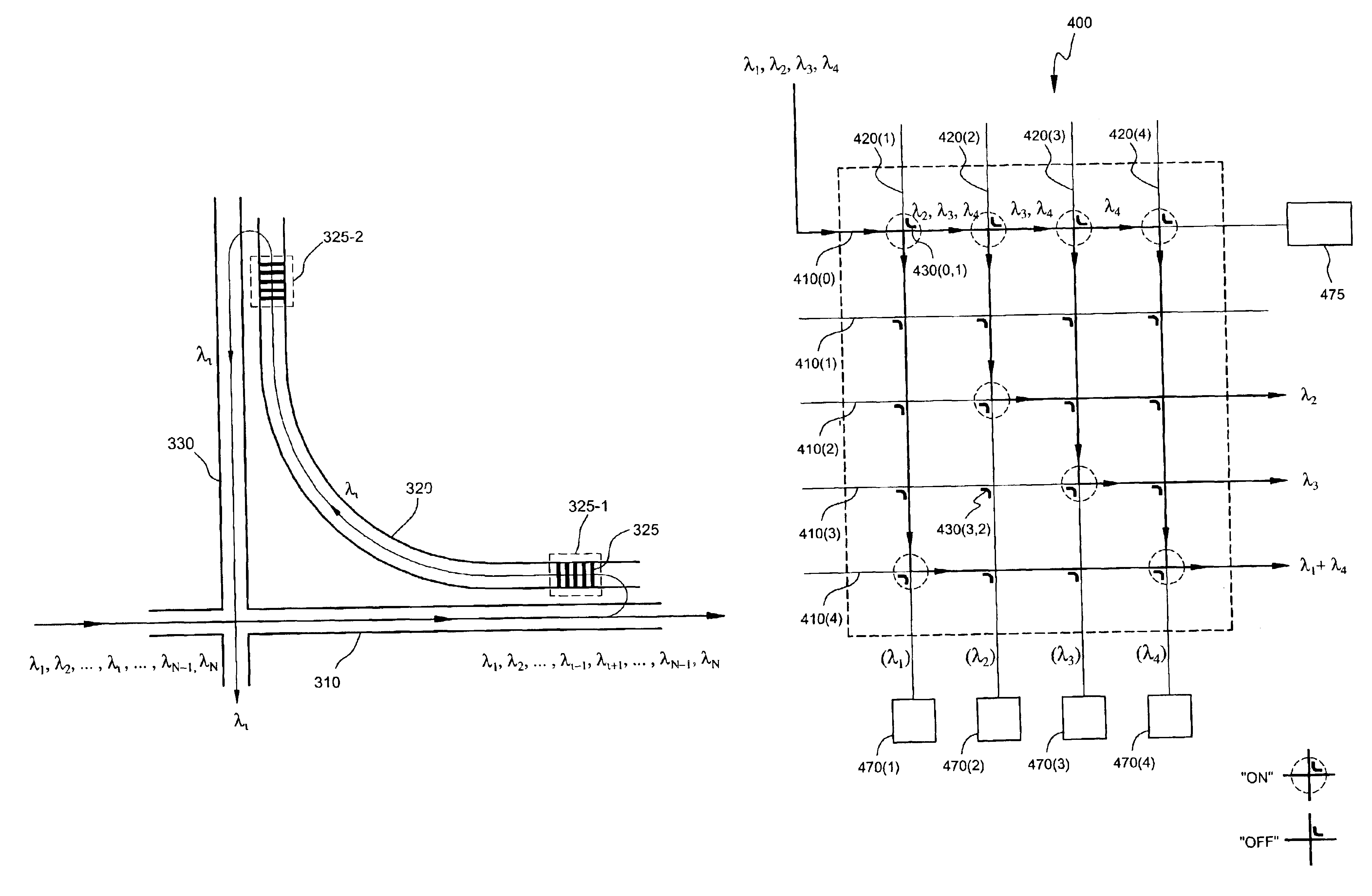
"The present invention is about a method for making a MEMS-actuated waveguide grating-based wavelength selective switch. The switch is made on a silicon substrate and uses electrostatic bending of a waveguide with integrated Bragg gratings to selectively couple wavelengths of light into desired output waveguides. The method simplifies the production of large-scale optical switches and reduces the size and cost of the switches. The switch matrix performs the de-multiplexing and re-multiplexing functions, eliminating the need for external devices. The integrated Bragg gratings are formed by physically corrugating a waveguide, which makes them smaller and closer together than fiber-optic devices, opening the door for leveraging IC processing to fabricate the highly integrated optical switches."

Problems solved by technology

Current state of the art in optical switching and signal transmission systems are limited to optical switching of an entire spectral range without wavelength differentiation or selection.
This requirement leads to more complicate system configurations, higher manufacture and maintenance costs, and lower system reliability.
However, with the current technical limitations, all fiber network systems implemented with optical switches are still quite expensive.
However, devices built using current TFF technology have the following disadvantages: they are difficult to manufacture when the spacing requirement is below 200 GHz; the packaging cost is very high; and the yield is low.
Meanwhile, the disadvantages are that AWG devices are prone to cross talk and their packaging is complex.
However, the FBG products available in the current market have relatively high power loss.
Moreover, each channel requires a circulator, which increases component costs and possibly increases packaging costs.
On the other hand, these products and their methods of use are disadvantageous in the following aspects: first, in these switches, light travels through free space, which causes unbalanced power loss.
Secondly, in order to steer each mirror, three to four electrodes need to be connected to each mirror, which is a major challenge to produce large-scale mechanical-type MEMS-based switches.
Thirdly, alignment and packaging are difficult tasks particularly for large-scale switches.
The disadvantages of these devices are their reliability issues and the insertion loss issue for the large-scale switches.
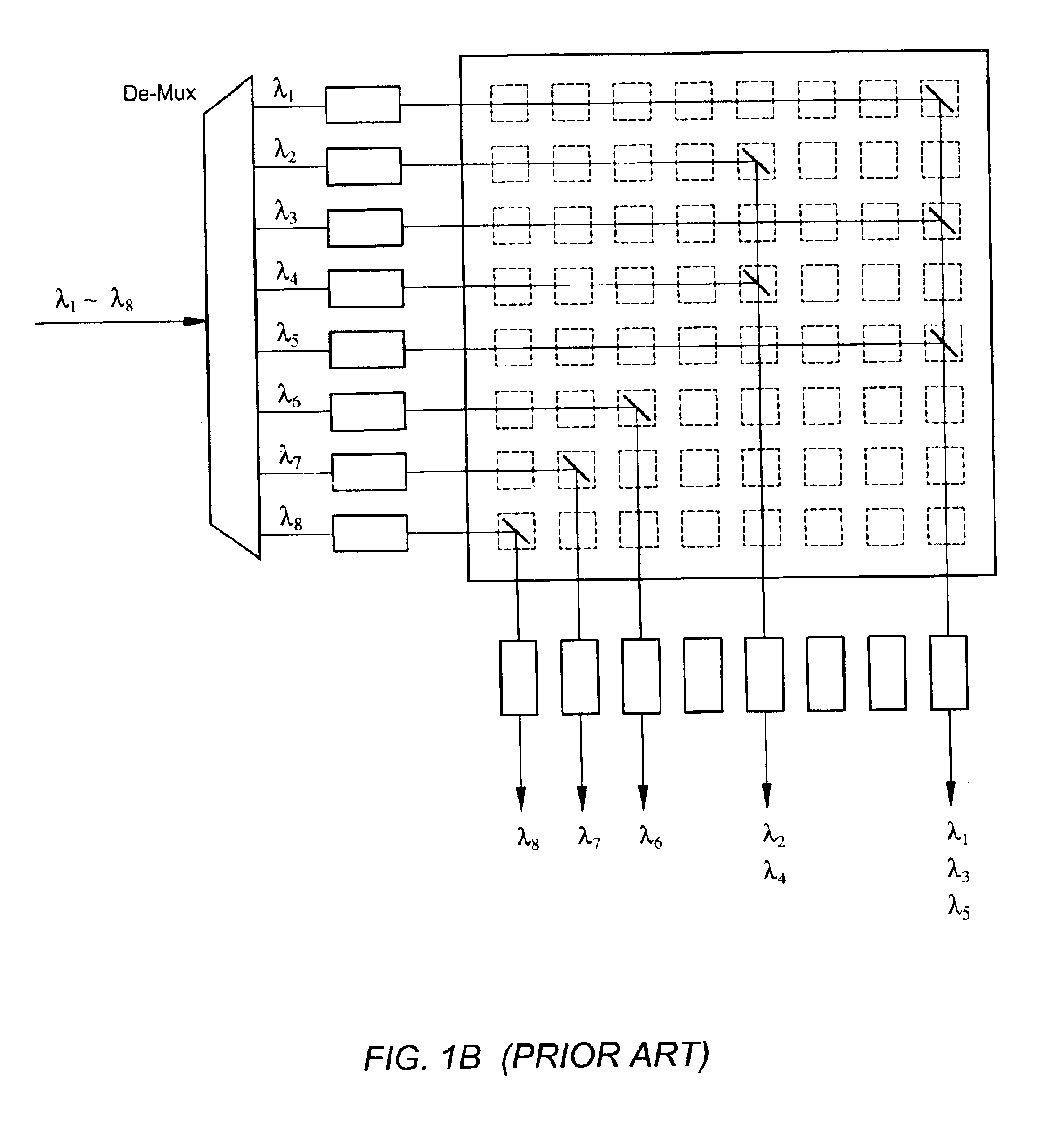
A common drawback of both of these two types of MEMS-based switches is the requirement to work with external de-multiplexing and re-multiplexing devices in order to function properly in an optical networking system.
The requirements of implementing de-multiplexing and re-multiplexing functions add tremendous complexities to the system configuration and significantly increase the cost of manufacture, system installation, and maintenance of the optical network systems.
Another drawback of both of these two types of MEMS-based switches is that these prior-art switching systems are not wavelength selective switches.
In another word, the switching systems cannot selectively switch a particular wavelength from an input waveguide to a desired output waveguide.
In short, they are not wavelength intelligent devices.
However, since in order to switch the optical signal transmission requires a control of the routing of the optical transmission, an operational characteristic of wavelength selection alone is not sufficient to build an optical switch.

Method used


Image

  • Waveguide grating-based wavelength selective switch actuated by micro-electromechanical system
  • Waveguide grating-based wavelength selective switch actuated by micro-electromechanical system
  • Waveguide grating-based wavelength selective switch actuated by micro-electromechanical system

Examples


Embodiment Construction

In the following description, numerous specific details are provided, such as the identification of various system components, to provide a thorough understanding of embodiments of the invention. One skilled in the art will recognize, however, that the invention can be practiced without one or more of the specific details, or with other methods, components, materials, etc. In still other instances, well-known structures, materials, or operations are not shown or described in detail to avoid obscuring aspects of various embodiments of the invention. Reference throughout this specification to “one embodiment” or “an embodiment” means that a particular feature, structure, or characteristic described in connection with the embodiment is included in at least one embodiment of the present invention. Thus, the appearance of the phrases “in one embodiment” or “in an embodiment” in various places throughout this specification are not necessarily all referring to the same embodiment. Furtherm...


PUM


Abstract

The present invention is a wavelength-selective optical switching system. The switching system includes an input waveguide designated as waveguide WG(0) for receiving a multiplexed optical signal comprising optical signals transmitted over a plurality of wavelength channels represented by λ1, λ2, λ3, , λN, where N is a positive integer wherein the input waveguide extending over a first direction. The switching system further includes a two dimensional waveguide array comprising a plurality of first direction waveguides WG(i), i=1, 2, 3, , M extending over the first direction substantially parallel to the input waveguide WG(0) where M is a positive integer and a plurality of second direction waveguides WG′(j), j=1, 2, 3, N, extending over a second direction substantially perpendicular to the first direction and intersecting with the input waveguide and each of the first direction waveguide WG(i), i=0, 1, 2, 3, ,M, thus forming (M+1)×N intersections. The switching system further includes a plurality of wavelength selective grating-based switches SW(i, j) where i=0, 1, 2, 3, , M and j=1, 2, 3, , N, each disposed on one of the (M+1)×N intersections for selectively transmitting an optical signal of wavelength λj into a waveguide WG′(j) and for selectively transmitting an optical signal of a predefined combination of wavelengths into at least one of the waveguide WG(i) for i=1, 2, 3, M.

Description

BACKGROUND OF THE INVENTION1. Field of the InventionThis invention relates generally to technologies for switching and routing optical wavelengths. More particularly, this invention relates to innovative method, structures and processes to manufacture micro-electromechanical system (MEMS)-actuated, waveguide grating-based wavelength selective switches.2. Description of the Related ArtCurrent state of the art in optical switching and signal transmission systems are limited to optical switching of an entire spectral range without wavelength differentiation or selection. Due to the lack of wavelength selection, an optical switch operation must frequently operate with a wavelength de-multiplexing and multiplexing device to achieve a purpose of transferring optical signals of different wavelengths to different ports. This requirement leads to more complicate system configurations, higher manufacture and maintenance costs, and lower system reliability. For this reason, even that optical s...

Claims


Application Information

Patent Timeline
Patent Type & Authority Patents(United States)
IPC IPC(8): G02B6/124G02B6/35G02B6/34H04Q11/00G02B6/28G02B6/12
CPCG02B6/124G02B6/3508G02B6/3536H04Q11/0005G02B6/2852H04Q2011/0049G02B6/357G02B2006/12107G02B6/3546
Inventor ZHANG, JIANGJUNLING, PEICHINGCHEN, JINLIANGXU, MING
Owner OPLUN
Learn More