Exhaust emission control system for multiple cylinder internal combustion engine

a technology of exhaust emission control and internal combustion engine, which is applied in the direction of exhaust treatment electric control, electrical control, machines/engines, etc., can solve the problems of difficult to detect a slight deterioration of the catalyst, the module cycle is set to a relatively short cycle, and the catalyst is difficult to detect a slight deterioration, etc., to achieve high exhaust emission control performance

Inactive Publication Date: 2005-01-11
MITSUBISHI MOTORS CORP
View PDF7 Cites 4 Cited by
  • Summary
  • Abstract
  • Description
  • Claims
  • Application Information

AI Technical Summary

Benefits of technology

As a result, it is possible to determine whether the catalytic converters have deterio

Problems solved by technology

According to the above-described conventional catalyst deterioration detecting method, however, the modulation cycle is set to a relatively short cycle due to the relation with the operational performance of the internal combustion engine.
Since only a small amount of oxygen can be occluded on such a short modulation cycle and there is only a slight variation in t

Method used


Image

  • Exhaust emission control system for multiple cylinder internal combustion engine
  • Exhaust emission control system for multiple cylinder internal combustion engine
  • Exhaust emission control system for multiple cylinder internal combustion engine

Examples


Embodiment Construction

The present invention will now be described in detail with reference to the drawings showing an embodiment thereof.

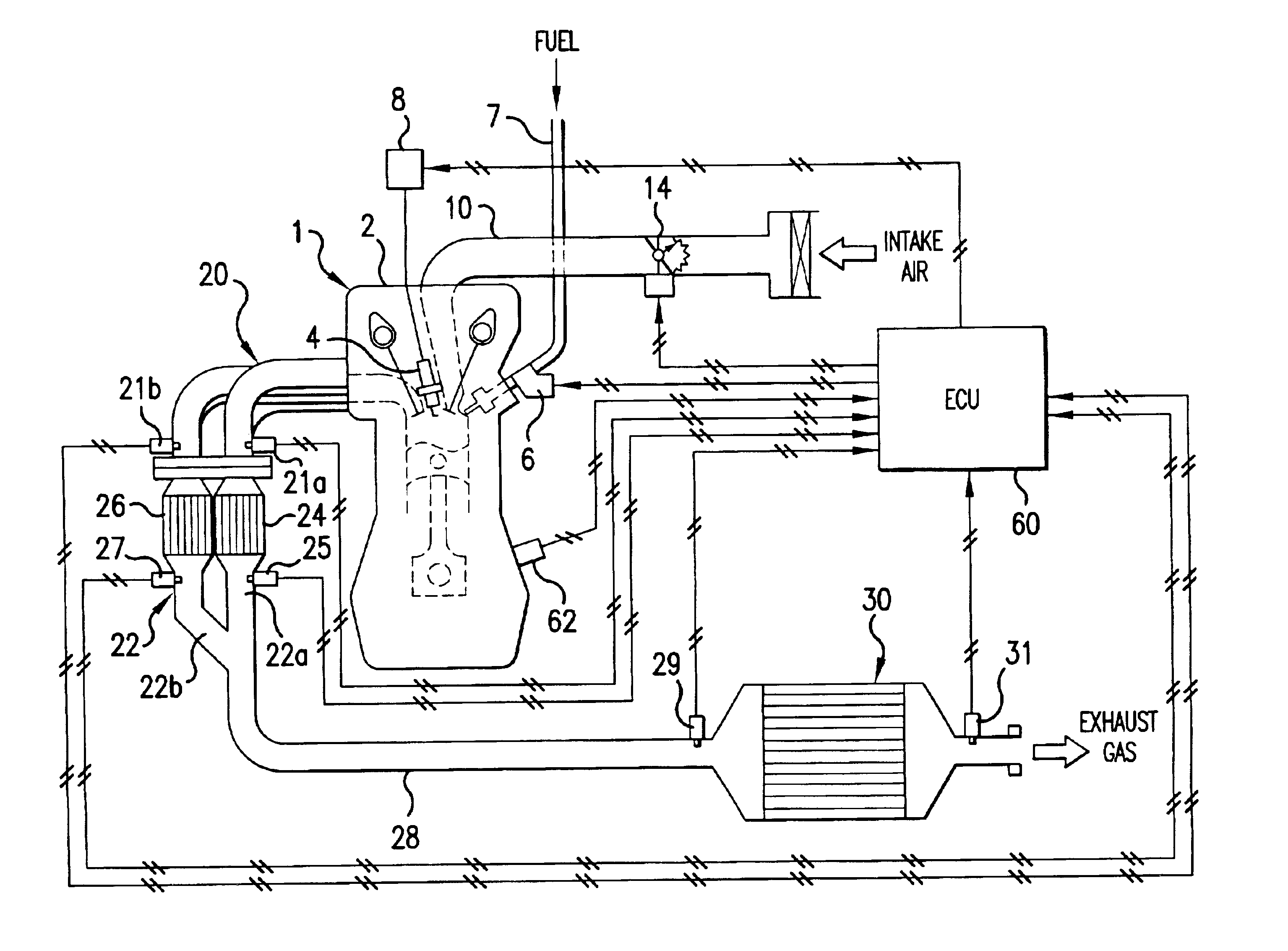
FIG. 1 is a schematic diagram showing the construction of an exhaust emission control system for a multiple cylinder internal combustion engine according to the embodiment of the present invention. A description will now be given of the construction of the exhaust emission control system with reference to FIG. 1.

As shown in FIG. 1, a cylinder injection type spark ignition 4-cycle 4-cylinder gasoline engine capable of performing fuel injection in an intake stroke (intake stroke injection) and in a compression stroke (compression stroke injection) by switching the fuel injection mode, for example, is employed as an engine main body (hereinafter referred to as “engine”) 1 as a multiple cylinder internal combustion engine. The cylinder injection type engine 1 is capable of operating at a stoichiometric air-fuel ratio, a rich air-fuel ratio (rich air-fuel ratio operation), a...


PUM


Abstract

An exhaust emission control system for an internal combustion engine includes an exhaust air-fuel ratio changing device switching the exhaust air-fuel ratio of exhaust gas flowing into one of an upstream exhaust passages and the exhaust air-fuel ratio of exhaust gas flowing into the other one of the upstream exhaust passages to a rich air-fuel ratio and to a lean air-fuel ratio alternately on a predetermined cycle longer than each of combustion cycles of the internal combustion engine, to thereby determine whether upstream catalytic converters have deteriorated or not according to a change in the exhaust air-fuel ratio outputted by upstream exhaust sensors provided downstream of the upstream catalytic converters. Therefore, it is possible to surely determine whether catalytic converters have deteriorated even slightly or not while ensuring a high exhaust emission control performance.

Description

CROSS-REFERENCE TO THE RELATED APPLICATIONThis application incorporates by reference the subject matter of Application No. 2002-54552 filed in Japan on Feb. 28, 2002, on which a priority claim is based on under 35 U.S.C. § 119(a).BACKGROUND OF THE INVENTION(1) Field of the InventionThe present invention relates to an exhaust emission control system for a multiple cylinder internal combustion engine. In particular, the present invention relates to the technique for determining whether a catalytic converter has deteriorated or not.(2) Description of the Related ArtConventionally, considering that the oxygen storage capacity of a catalyst in a catalytic converter for exhaust emission control is correlated closely with the catalyst performance (mainly the HC purifying performance), whether the catalytic converter containing a large amount of oxygen occluding substances such as cerium (Ce) has deteriorated or not is determined by monitoring a change in the oxygen storage performance with...

Claims


Application Information

Patent Timeline
IPC IPC(8): F01N11/00F01N7/04F01N7/00F01N7/02F01N3/20F02D45/00F01N3/28F01N13/02F01N13/04F02D41/14
CPCF01N3/101F01N11/007F01N13/011F01N13/0093F01N13/009F01N2550/02F01N2900/0422Y02T10/22Y02T10/47Y02T10/12Y02T10/40F01N3/10
Inventor TAMURA, YASUKI
Owner MITSUBISHI MOTORS CORP
Why Eureka
Try Eureka