
Method of, system for, and computer program product for providing efficient utilization of memory hierarchy through code restructuring

Inactive Publication Date: 2005-01-04
IBM CORP
View PDF11 Cites 48 Cited by
  • Summary
  • Abstract
  • Description
  • Claims
  • Application Information

AI Technical Summary

Benefits of technology

The present invention reorders code to reduce communications across cache line and across page boundaries. The present invention also reorders code to reduce the likelihood that chunks of code that communicate with each other and that have the same cache or TLB associativity set will be assigned to different cache lines or pages. The present invention may be generalized to deal with multiple levels of cache or other types of memory hierarchy.
The present invention has the further advantage of being extendable to deal with additional memory hierarchies, such as second level (L2) or higher caches that may be introduced in future machines.

Problems solved by technology

Ensuring effective usage is difficult for large programs like compilers or database engine codes that have complex control flow.
Consequently, code generated for large complex programs consists of sections that are heavily executed intermingled with sections that are infrequently executed, resulting in poor utilization of the memory hierarchy.
If the working set fits in the cache, this approach is reasonable, on the other hand, if the cache is small or if the effective portion of the cache available to an application is small due to multiprogramming, conventional code restructuring techniques may not perform well.
A major flaw of these conventional approaches is that “closeness” in memory does not actually relate to cache or paging performance.
Two basic blocks may be “close” together in memory, and yet there may still be a cache miss or page fault transitioning between the two basic blocks, or they may be very far apart and still cause the same effect of a cache miss or page fault.
Thus, conventional code restructuring techniques fail to realize that blocks interacting frequently should be kept in the same cache line or page rather than “close” to each other in memory.
Conventional code restructuring techniques also fail to realize that memory hierarchy hardware parameters such as cache line size, page size, cache associatively size and translation lookaside buffer (TLB) size may be considered in determining the code structure of an application.
Thus, the conventional code restructuring techniques fail to consider memory hierarchy.

Method used


Image

  • Method of, system for, and computer program product for providing efficient utilization of memory hierarchy through code restructuring
  • Method of, system for, and computer program product for providing efficient utilization of memory hierarchy through code restructuring
  • Method of, system for, and computer program product for providing efficient utilization of memory hierarchy through code restructuring

Examples


Embodiment Construction

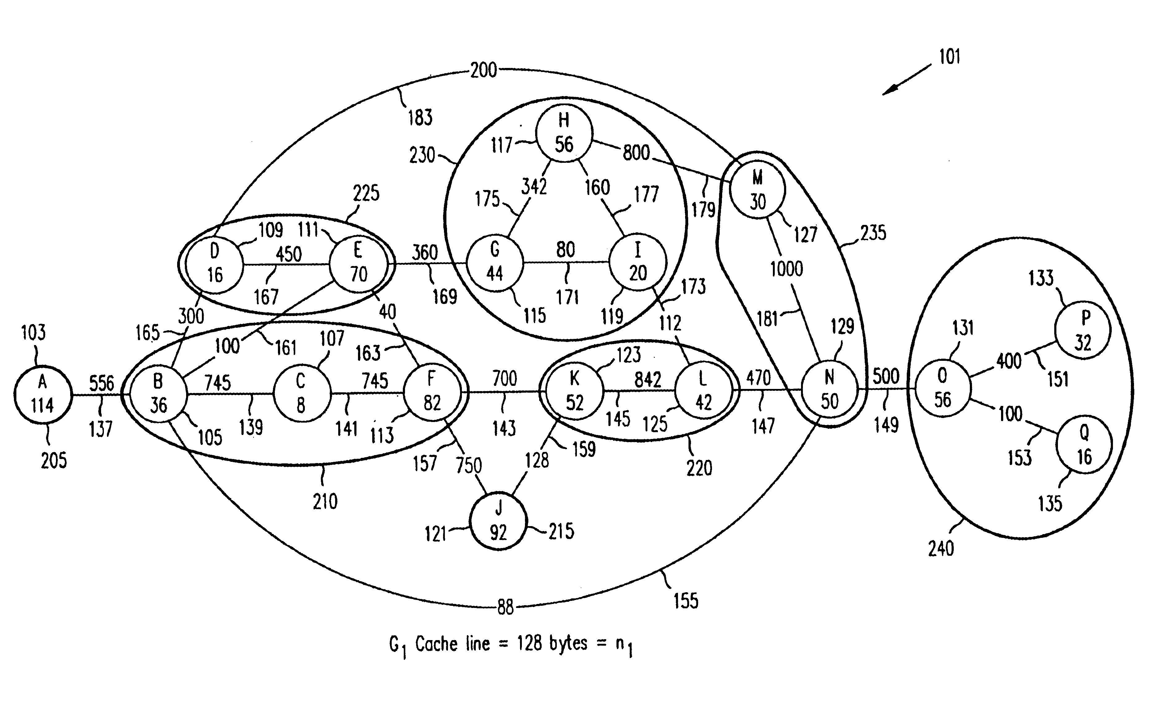
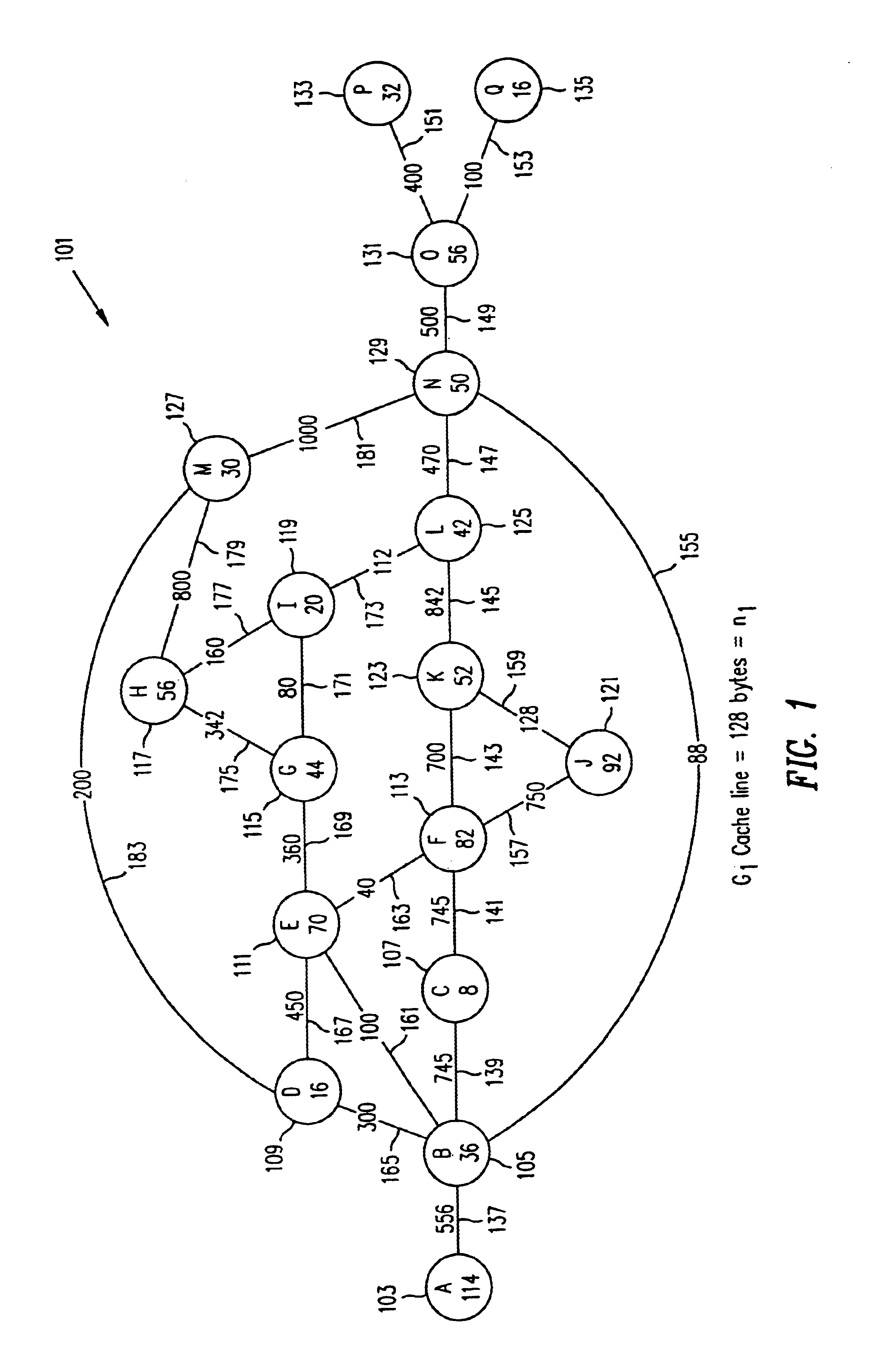
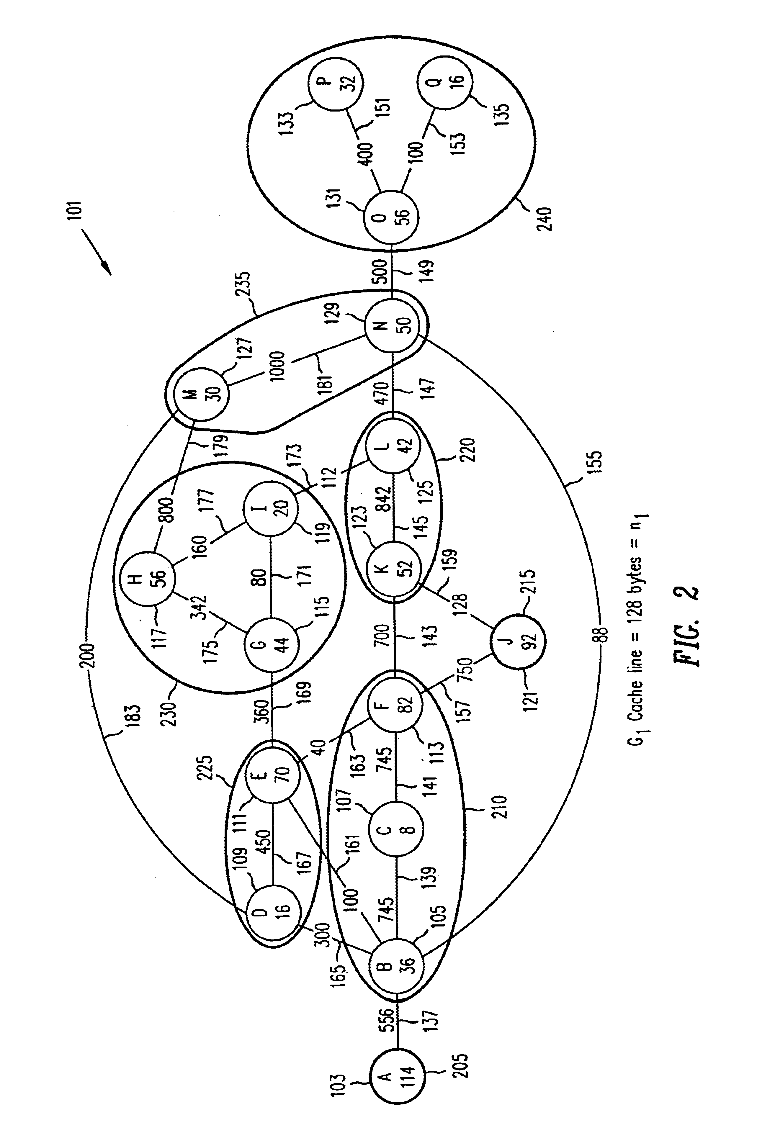
Referring now to FIG. 1 through FIG. 5, sample Program Execution Graphs are shown to illustrate the practice of the present invention. The control flow and frequency information of the profiled program is organized in the form of a Program Execution Graph (PEG) which is a weighted undirected graph. For example, FIG. 1 illustrates a PEG G1, generally referred to as 101, where Gi=(V1, E1). A node in the set of nodes V1 corresponds to a basic block that has been executed at least once during profiling. For G1 101, the set of nodes V1 comprises the set {A 103, B 105, C 107, D 109, E 111, F 113, G 115, H 117, I 119, J 121, K 123, L 125, M 127, N 129, O 131, P 133, and Q 1135}. An edge (u, v), in the set of edges E1, between nodes u and v implies that there is some transition that occurs during profiling between the two basic blocks represented by u and v. For G1 100, the set of nodes E1 comprises the set {(A, B) 137, (B, C) 139, (C, F) 141, (F, K) 143, (K, L) 145, (L, N) 147, (N, O) 149,...


PUM


Abstract

Code restructuring or reordering based on profiling information and memory hierarchy is provided by constructing a Program Execution Graph (PEG) corresponding to a level of the memory hierarchy, partitioning this PEG to reduce estimated memory overhead costs below an upper bound, and constructing a PEG for a next level of the memory hierarchy from the partitioned PEG. The PEG is constructed from control flow and frequency information from a profile of the program to be restructured. The PEG is a weighted undirected graph comprising nodes representing basic blocks and edges representing transfer of control between pairs of basic blocks. The weight of a node is the size of the basic block it represents and the weight of an edge is the frequency of transition between the pair of basic blocs it connects.

Description

STATEMENT AS TO RIGHTS TO INVENTIONS MADE UNDER FEDERALLY SPONSORED RESEARCH AND DEVELOPMENTA portion of the Disclosure of this patent document contains material which is subject to copyright protection. The copyright owner has no objection to the facsimile reproduction by anyone of the patent document or the patent disclosure, as it appears in the Patent and Trademark Office patent file or records, but otherwise reserves all copyright rights whatsoever.BACKGROUND OF THE INVENTION1. Field of the InventionThis invention relates generally to optimizing compilers for development of computer programs for use on a computer, and more particularly to code restructuring.2. Description of the Related ArtAdvances in processor designs have provided very high speed instruction processing. In order to sustain this speed, processors need very effective usage of the memory hierarchy of the machines. Ensuring effective usage is difficult for large programs like compilers or database engine codes th...

Claims


Application Information

Patent Timeline
IPC IPC(8): G06F9/45
CPCG06F8/4442
Inventor JU, DZ CHINGMUTHUKUMAR, KALYANRAMASWAMY, SHANKARSIMONS, BARBARA BLUESTEIN
Owner IBM CORP
Learn More