Manufacturing method of a muffler assembly
a manufacturing method and muffler technology, applied in the field of manufacturing methods, can solve the problems of difficult reduction of manufacturing costs and bad work environmen
- Summary
- Abstract
- Description
- Claims
- Application Information
AI Technical Summary
Benefits of technology
Problems solved by technology
Method used
Image

Examples
fourth embodiment
FIG. 4 shows the muffler assembly (4) that is manufactured by the method of the present invention. The muffler assembly of the embodiment comprises a cylinder (41) that has a first end forged to form an inlet pipe (42) and a second end forged to form an exhaust pipe (43). A muffling device (44) is received in the cylinder (41) and muffling material (45) fills the space between the muffling device (44) and an inner periphery of the cylinder (41). The muffling device (44) is spirally made of pipe material and has a length longer than that of the cylinder (41), such that the muffling device (44) forms multiple curves after being mounted in the cylinder (41). The muffling device (44) has multiple through holes (44a) formed therein such that sound waves are partially eliminated via the through holes (44a) and the muffling material (45) when the sound wave passes through the muffling device (44).
fifth embodiment
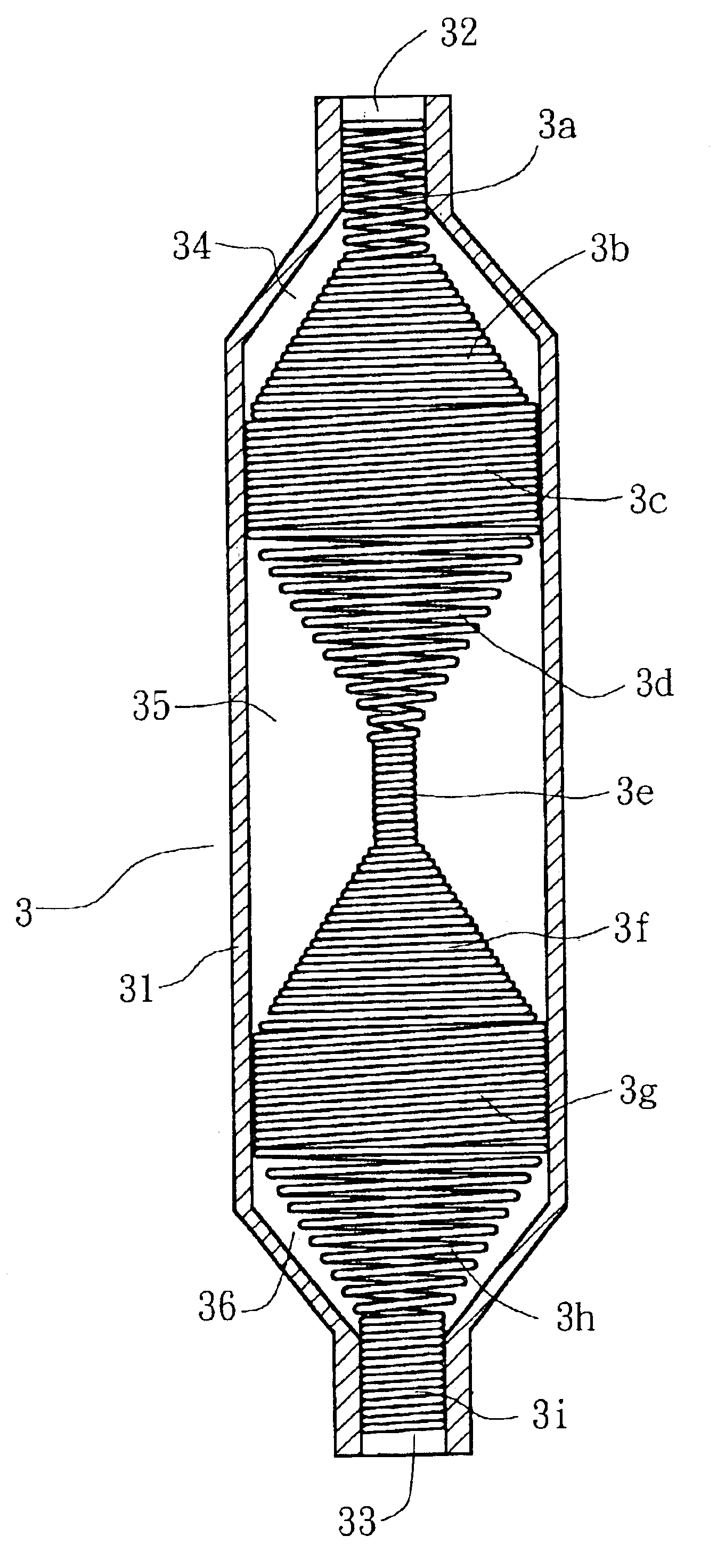
With reference to FIG. 5, the muffler assembly that is manufactured by the method of the present invention is shown. The muffler assembly (5) of the embodiment comprises a cylinder (51) having a first end forged to form an inlet pipe (52) and a second end forged to form an exhaust pipe (53). The cylinder (51) has a first resonance chamber (54), a second resonance chamber (55), a swell chamber (56) and a third resonance chamber (57). A muffling device (58) is longitudinally received in the cylinder (51) and has two opposite ends respectively secured in the inlet pipe (52) and the exhaust pipe (53) of the cylinder (51). The muffling device (58) has a first swell chamber (58a) separating the first resonance chamber (54) from the second resonance chamber (55), a second swell chamber (58b) separating the second resonance chamber (55) from the swell chamber (56) and a third swell chamber (58c) separating the swell chamber (56) from the third resonance chamber (57). The first swell chamber...
sixth embodiment
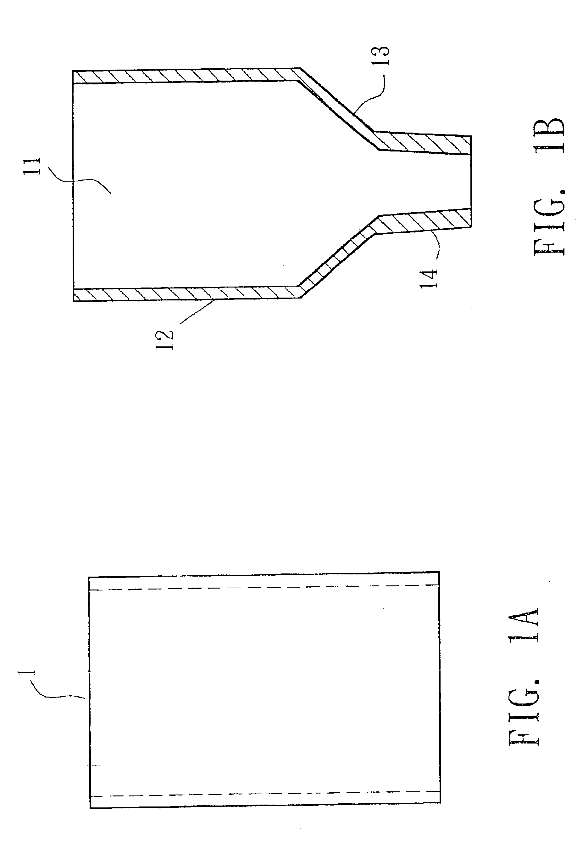
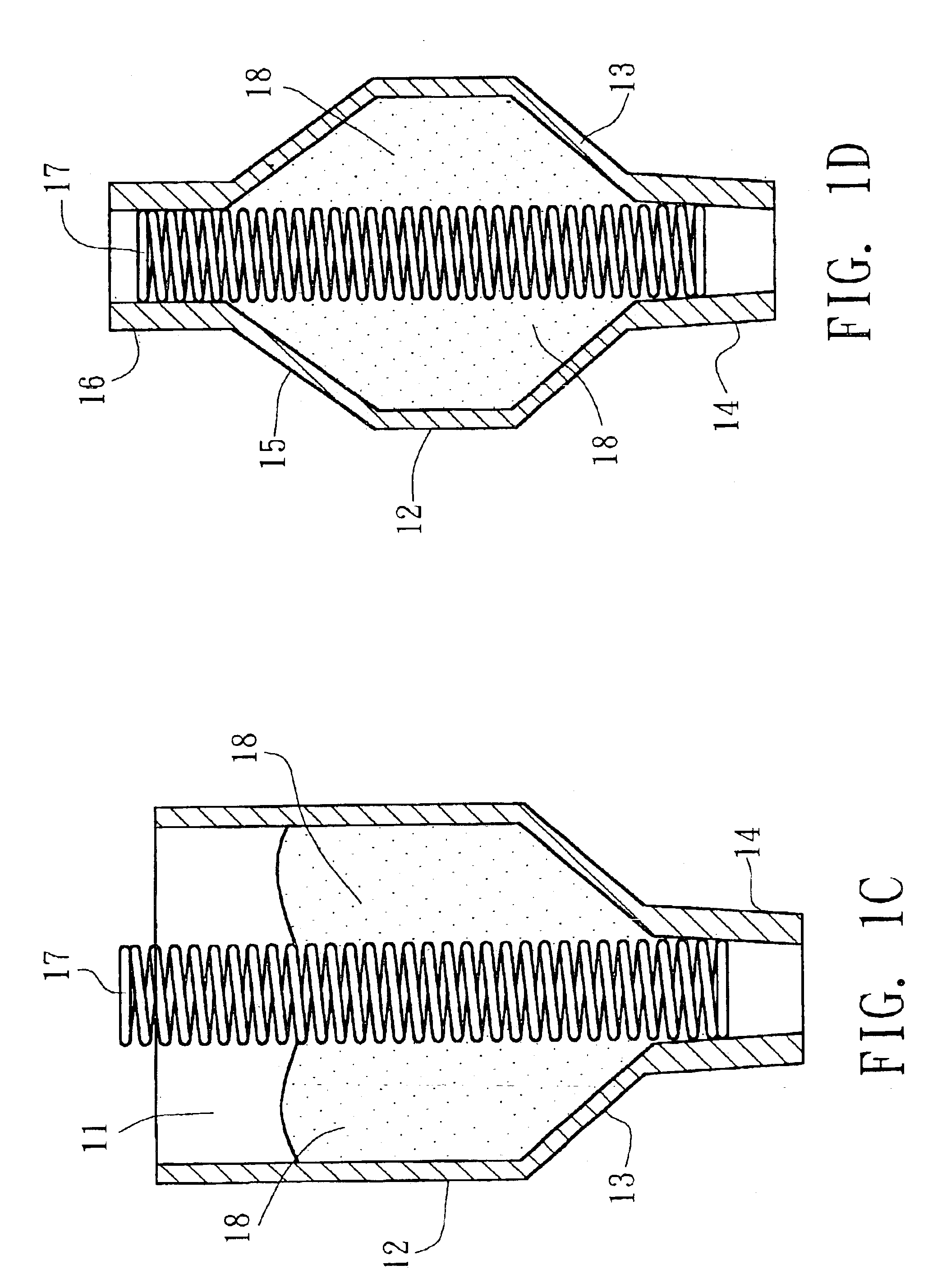
FIGS. 6A-6D show the muffler assembly that is manufactured by the method of the present invention. The muffler assembly (6) of the embodiment comprises a cylinder (61) having a first end forged to from an inlet pipe (62), a second end forged to formed an exhaust pipe (63) and a swell chamber (67) defined in the cylinder (61) between the two opposite ends of the cylinder (61). A muffling device (64) is longitudinally received in the swell chamber (67) and the exhaust pipe (63). The muffling device (64) is made of a metal strap that is spirally wound along an outer periphery of a funnel-shaped mold (66) to form a passage (65) in the muffling device (64). A series of through holes (64a) are formed in the muffling device (64). Consequently, sound waves expand and are partially eliminated in the swell chamber (67) and gradually compressed to be partially eliminated when passing through the through holes (64a) of the muffling device (64). Finally, the residual sound waves are exhausted vi...
PUM
| Property | Measurement | Unit |
|---|---|---|
| length | aaaaa | aaaaa |
| diameter | aaaaa | aaaaa |
| area | aaaaa | aaaaa |
Abstract
Description
Claims
Application Information
 - R&D
- Intellectual Property
- Life Sciences
- Materials
- Tech Scout
- Unparalleled Data Quality
- Higher Quality Content
- 60% Fewer Hallucinations
Browse by: Latest US Patents, China's latest patents, Technical Efficacy Thesaurus, Application Domain, Technology Topic, Popular Technical Reports.
© 2025 PatSnap. All rights reserved.Legal|Privacy policy|Modern Slavery Act Transparency Statement|Sitemap|About US| Contact US: help@patsnap.com