
Method and apparatus for clock gating clock trees to reduce power dissipation

Active Publication Date: 2004-11-23
KEYSIGHT TECH
View PDF7 Cites 39 Cited by
  • Summary
  • Abstract
  • Description
  • Claims
  • Application Information

AI Technical Summary

Benefits of technology

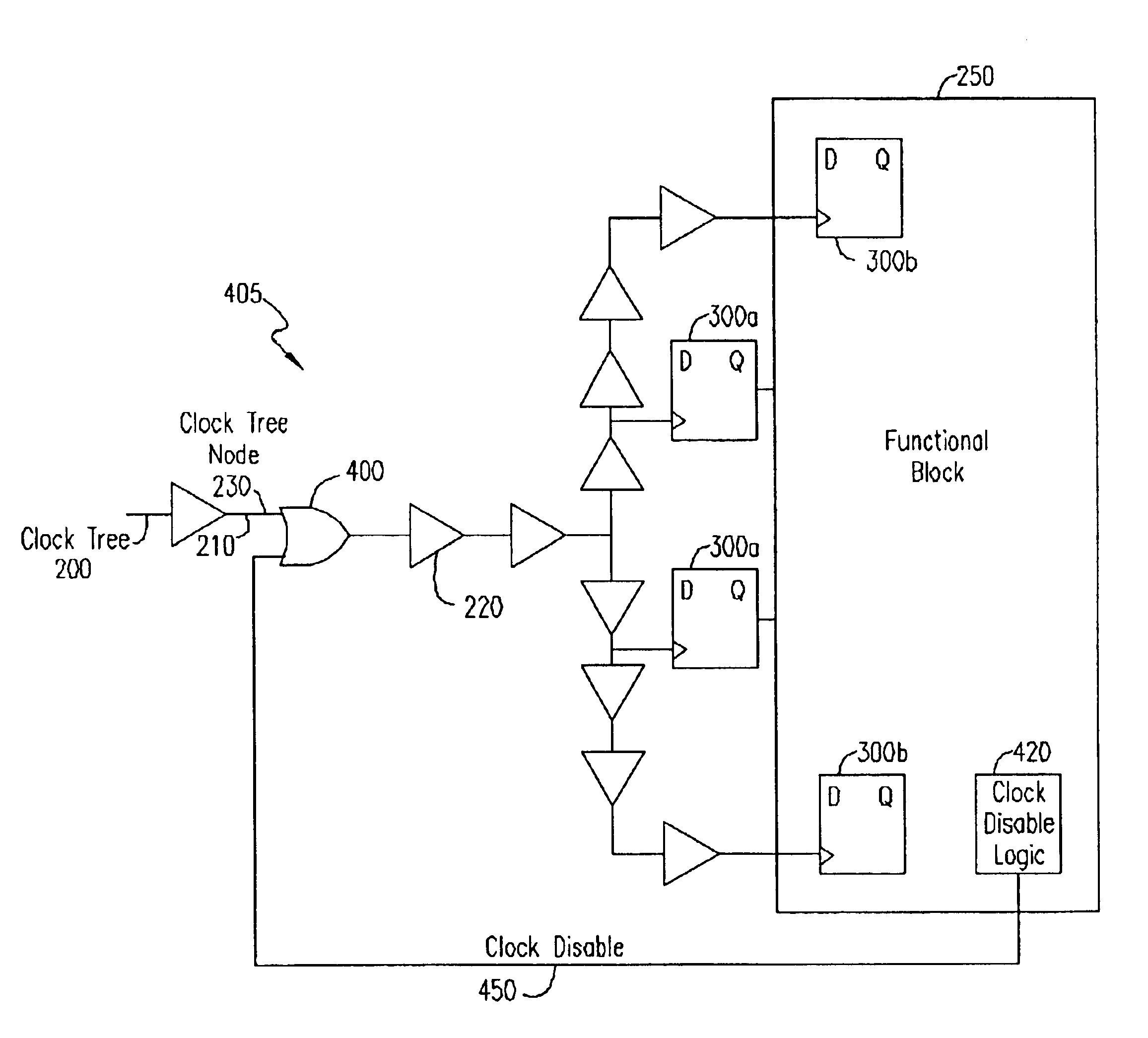
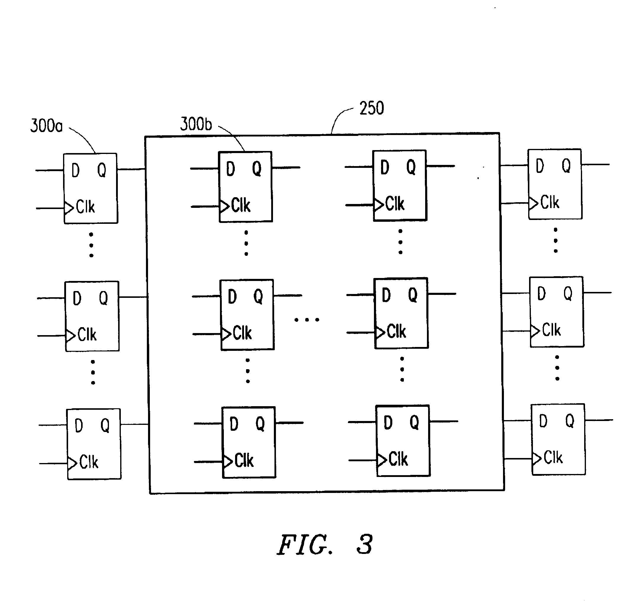
In one embodiment, the functional block generates the clock disable signal while in an idle state. The functional block determines whether the next operating state is an idle state based upon the current state and the value of the input signals to the functional block. Each functional block includes combinational logic and one or more clocked external flip-flops. The clock disable signal gates the clock signal to the external flip-flops to prevent switching of the external flip-flops. In addition, the clock disable signal gates the clock signal to any internal flip-flops within the functional block to further reduce power consumption in the digital circuit.
In further embodiments, the digital circuit is a pipeline circuit having multiple functional blocks interconnected in a pipeline design. Each functional block generates a respective clock disable signal to gate the clock signal to each functional block independently of other functional blocks within the pipeline. Additional embodiments include a global signal generator for providing a global signal to each of the functional blocks to prevent the generation of clock disable signals, when necessary, such as during testing of chips.

Problems solved by technology

However, neither Simmons et al. nor Long et al. address the power dissipation resulting from the switching elements within the clock tree feeding the functional blocks.
Thus, conventional clock-gating circuits do not sufficiently reduce the power consumption in digital circuits.
Other efforts at improving the clock tree efficiency with gated clocks also have not adequately or effectively reduced the power consumption in traditional digital circuits.
Both Minami et al. and Dean et al. present complicated circuit design techniques that are not easily implemented into existing digital circuits.
Therefore, neither Mianami et al. nor Dean et al. provide a suitable solution for reducing power consumption requirements in traditional digital circuits.

Method used


Image

  • Method and apparatus for clock gating clock trees to reduce power dissipation
  • Method and apparatus for clock gating clock trees to reduce power dissipation
  • Method and apparatus for clock gating clock trees to reduce power dissipation

Examples


Embodiment Construction

The numerous innovative teachings of the present application will be described with particular reference to the exemplary embodiments. However, it should be understood that these embodiments provide only a few examples of the many advantageous uses of the innovative teachings herein. In general, statements made in the specification do not necessarily delimit any of the various claimed inventions. Moreover, some statements may apply to some inventive features, but not to others.

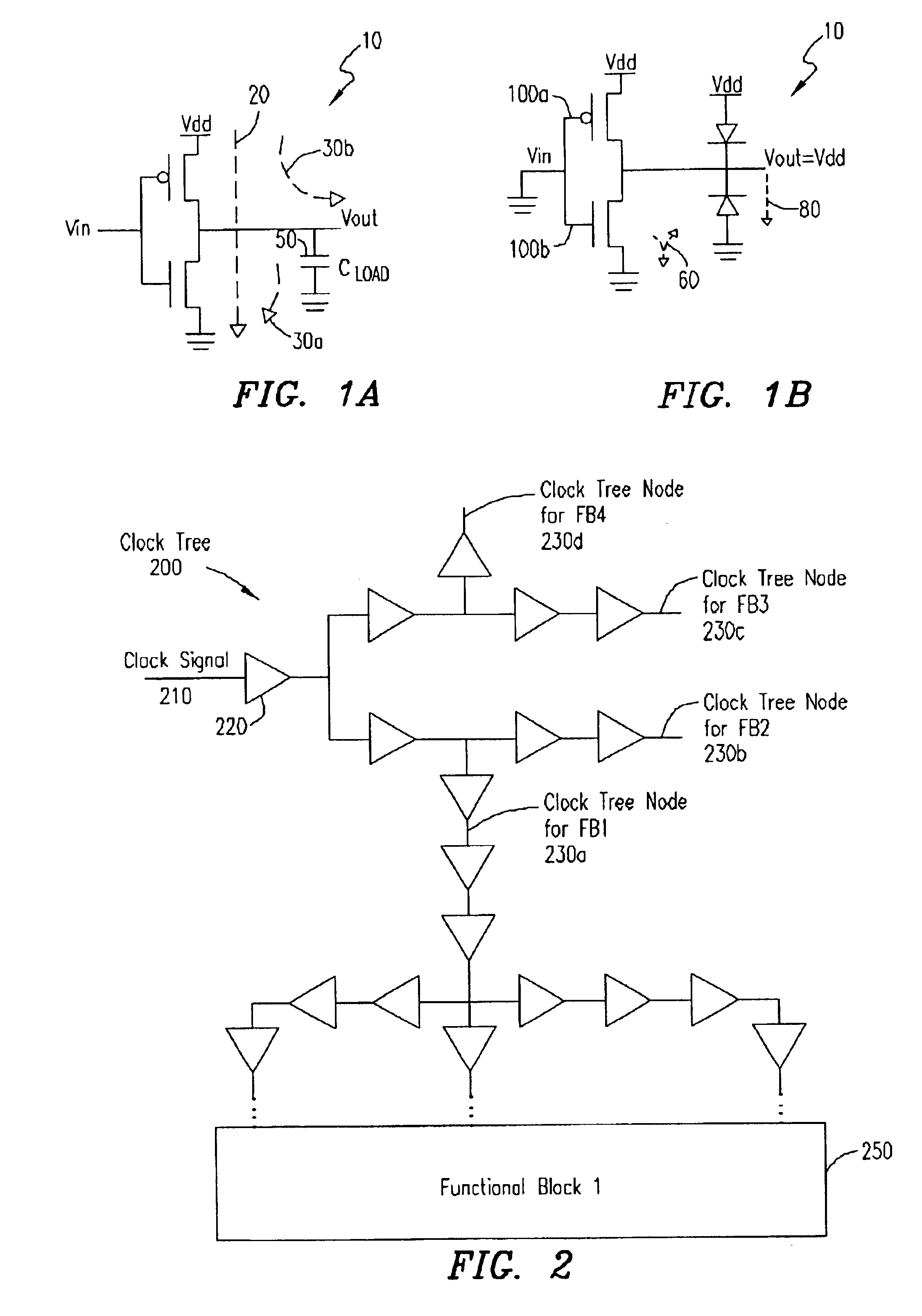
Power consumption in digital circuits can be classified as either dynamic power consumption or static power consumption. Dynamic power consumption is the dominant power consumption component and is a result of the capacitive nodes within a digital circuit switching. For example, referring to FIG. 1A, a CMOS digital circuit 10 having a capacitive node 50 is illustrated. The dynamic power dissipation in the circuit 10 is a function of the capacitive charging switching current 30b, the capacitive discharging swit...


PUM


Abstract

A clock gating circuit reduces the power dissipation in a digital circuit including at least one functional block by gating the clock signal at an input to a clock tree feeding the functional block. The clock gating circuit includes a logic gate that receives a clock signal and a clock disable signal generated by the functional block, and gates the clock signal at the input to the clock tree feeding the functional block. Further, a global signal generator is provided to transmit a global signal to each of the functional blocks to prevent the generation of clock disable signals, when necessary, such as during testing of chips.

Description

1. Technical Field of the InventionThe present invention relates generally to clock gating circuits, and in particular to methods for gating clock distribution networks within digital circuits.2. Description of Related ArtDigital circuits have widespread applications in the computing industry. Recently, the demand for mobile computing devices, such as personal digital assistants (PDAs), cellular telephones and laptop computers, has increased significantly. Mobile computing devices typically rely on batteries for power, and therefore, a key specification for such devices is low power consumption. In addition to increasing the battery life, reducing the power consumption in mobile computing devices also reduces the amount of heat generated, which enables smaller computing devices to be produced with diminished cooling requirements.Significant power savings in such mobile computing devices can be obtained by reducing the amount of switching activity in the digital circuitry. In most di...

Claims


Application Information

Patent Timeline
IPC IPC(8): G06F1/32
CPCG06F1/3203G06F1/3237G06F9/3869G06F1/3287Y02B60/1282Y02B60/32Y02B60/1221Y02D10/00Y02D30/50
Inventor SRIKANTAM, VAMSI K.CLARK, II, AIRELL RICHARD
Owner KEYSIGHT TECH
Learn More