Enclosed fuel cell system and related method

Inactive Publication Date: 2004-10-26
MTI MICROFUEL CELLS
View PDF17 Cites 24 Cited by
  • Summary
  • Abstract
  • Description
  • Claims
  • Application Information

AI Technical Summary

Benefits of technology

The disadvantage of prior techniques have been overcome by the present invention in which a direct oxidation fuel cell system is sealed with an enclosure comprising one or more layers of material such as a plastic that conforms directly to the shape of the fuel cell system, and in many instances actually serves to shrink the size of the overall system. The enclosure is substantially comprised of a material that is non-reactive with the fuel substance used in the fuel cell. In accordance with one aspect of the invention, the material is a heat-sensitive, shrink wrap material that provides a good sealant to substantially prevent fuel such as methanol from escaping from the system. Yet, the enclosure is lightweight, substantially impermeable to fluids in the cell, and conforms substantially to the exterior body of the fuel cell system so that it adds little or no bulk to the fuel cell system. The enclosure also prevents water from leaking out of the system.
In accordance with another aspect of the invention, at least one of the materials selected for the enclosure is such that the enclosure acts as an air filter to resist environmental contaminants from entering the fuel cell system. In addition, the material selected is preferably gas permeable, liquid impermeable, so that carbon dioxide, a product of the anode reaction, can be released from the fuel cell system, or a part of the system and oxygen, a cathodic reactant, can be introduced into the cathode aspect of the fuel cell if desired, while still limiting or preventing the escape of any of the fluids within the enclosure and preventing liquids from the ambient environment from entering the fuel cell system.
Mechanical advantages are also provided by the enclosure of the present invention in that the enclosure can aid in aligning the various components of the fuel cell system. In addition, the enclosure material may be used to generate or maintain compression of the DMFC, or fasten the DMFC system to the device, which it is powering, minimizing the number of fasteners needed to establish adequate connection and adherence of the DMFC system to the device.

Problems solved by technology

However, because fuel processing is expensive and requires significant volume, reformer-based systems are presently limited to comparatively high power applications.
The overall reaction may be limited by the failure of either of these reactions to proceed to completion at an acceptable rate (more specifically, failure to oxidize the fuel mixture will limit the cathodic generation of water, and vice versa).
The adaptation of fuel cell systems to mobile uses, however, is not straightforward because of the technical difficulties associated with reforming most carbonaceous fuels in a simple, cost effective manner, and within acceptable form factors and volume limits.
Further, a safe and efficient storage means for substantially pure hydrogen (which is a gas under the relevant operating conditions) presents a challenge because hydrogen gas must be stored at high pressure and at cryogenic temperatures or in heavy adsorption matrices in order to achieve useful energy densities.
However, current packaging for maintaining the integrity of the fuel cell system can be bulky plastics that can be expected to consume approximately 15-30% of the overall size of the DMFC system, presenting challenges in meeting certain form factor requirements.
Furthermore, the materials selected for the packaging should not be reactive with the fuel solution or other reactants or byproducts in such a manner that the operation of the fuel cell could be compromised, or effectively halted.
These systems, however, do not address the needs of fuel cell systems that utilize a liquid fuel.
Further, the material, in some circumstances may be one that would cause the overall system to shut down and cease providing power to the device should a leak or water contamination occur.

Method used


Image

  • Enclosed fuel cell system and related method
  • Enclosed fuel cell system and related method
  • Enclosed fuel cell system and related method

Examples


Embodiment Construction

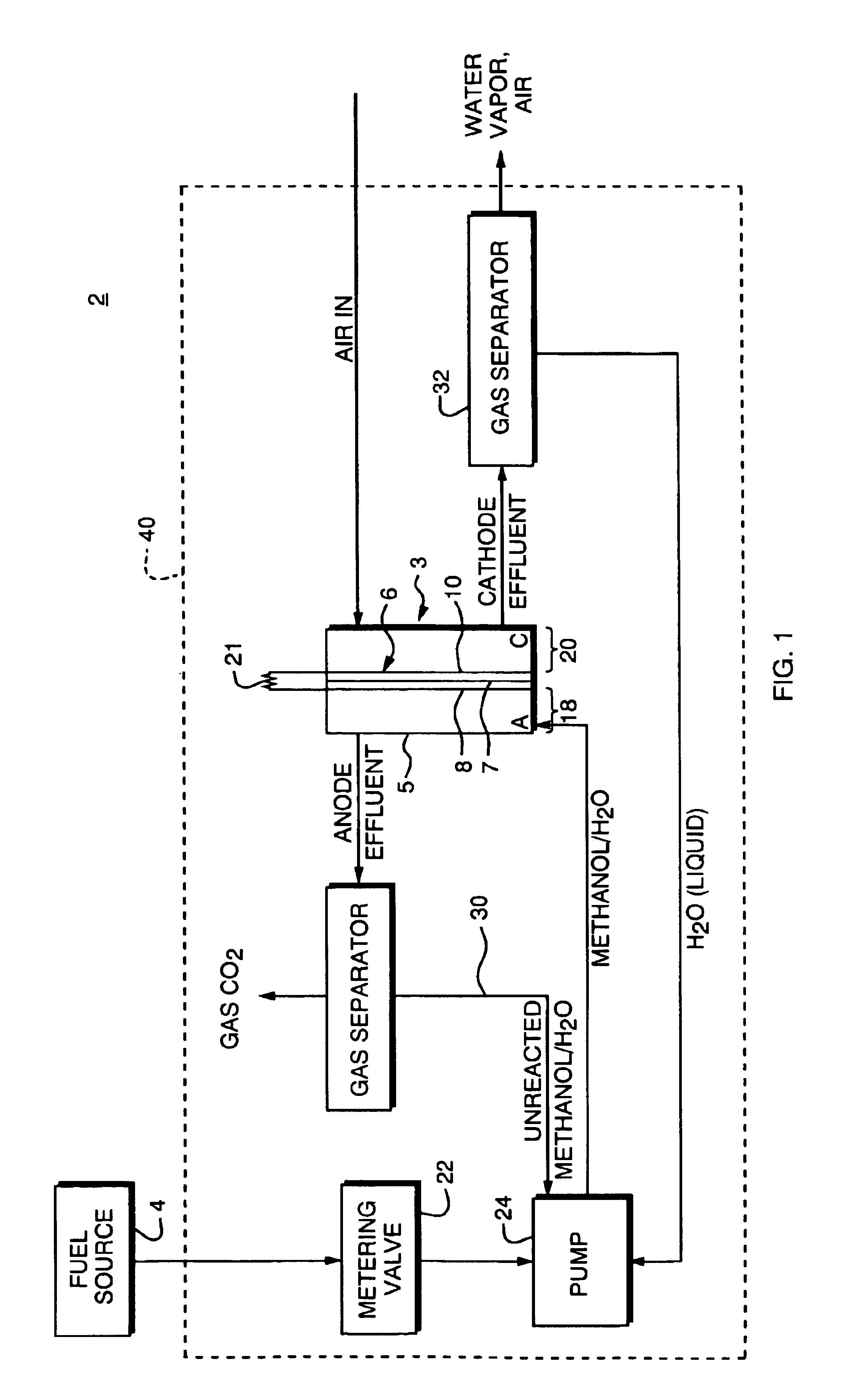
The present invention is an enclosed fuel cell system. The fuel used in the system may be any liquid carbonaceous fuel including, but not limited to, methanol, ethanol, and combinations or aqueous solutions thereof. For purposes of illustration, we herein describe an illustrative embodiment of the invention as it is employed in connection with a direct methanol fuel cell system ("DMFC"), with the fuel substance being methanol or an aqueous methanol solution. It should be understood, however, that it is within the scope of the present invention that the enclosed fuel cell system can be readily used with other fuels. Thus, as used herein, the word "fuel" shall include methanol, ethanol, or combinations or aqueous solutions thereof, and aqueous solutions thereof and other liquid carbonaceous fuels amenable to use in a direct oxidation fuel cell system.

For a better understanding of the invention, a direct methanol fuel cell system with which the invention could be employed will be brief...


PUM

PropertyMeasurementUnit
Poweraaaaaaaaaa
Coloraaaaaaaaaa
Shapeaaaaaaaaaa

Abstract

An enclosed direct oxidation fuel cell system is provided. The system is sealed with one or more layers of a plastic enclosure that conforms directly to the shape of the fuel cell system. The enclosure is substantially comprised of one or more layers of materials that are non-reactive with the fuel substance used in the fuel cell. In accordance with one aspect of the invention, one of the materials is a plastic film material that provides a good seal to substantially prevent liquids from escaping from the system. Yet, the enclosure is lightweight and conforms substantially to the exterior body of the fuel cell system so that it adds little or no bulk to the fuel cell system. The enclosure also prevents water from leaking out of the system. The enclosure materials may include color-changing properties so that in the event of a leak, it is visually apparent that liquid is in contact with the enclosure.

Description

1. Field of the InventionThis invention relates generally to direct oxidation fuel cell systems, and more particularly, to enclosures for such systems.2. Background InformationFuel cells are devices in which an electrochemical reaction is used to generate electricity. A variety of materials may be suited for use as a fuel depending upon the materials chosen for the components of the cell. Organic materials, such as methanol or natural gas, are attractive choices for fuel due to the their high specific energy.Fuel cell systems may be divided into "reformer-based" systems (i.e., those in which the fuel is processed in some fashion to extract hydrogen from the fuel before it is introduced into the fuel cell system) or "direct oxidation" systems in which the fuel is fed directly into the cell without the need for separate internal or external processing. Most stationary fuel cells are reformer-based fuel cell systems. However, because fuel processing is expensive and requires significan...

Claims


Application Information

Patent Timeline
IPC IPC(8): H01M8/04H01M8/06H01M8/24
CPCH01M8/04186H01M8/0662H01M8/247H01M8/2455H01M8/04089Y10T29/4911Y02E60/50
Inventor HIRSCH, ROBERT S.
Owner MTI MICROFUEL CELLS
Why Eureka
Try Eureka