
Press die

a press die and press technology, applied in the field of new press dies, can solve the problems of preventing affecting the general acceptance of the product, and easy cracking, so as to prevent the blank from becoming thin, prevent the blank from falling off, and improve the general acceptance

Inactive Publication Date: 2004-10-26
KOBE STEEL LTD
View PDF21 Cites 22 Cited by
  • Summary
  • Abstract
  • Description
  • Claims
  • Application Information

AI Technical Summary

Benefits of technology

It is an object of the present invention to provide a new press die which permits the blank to readily slide, and hence prevents the blank from becoming thin, and offers good press-formability.
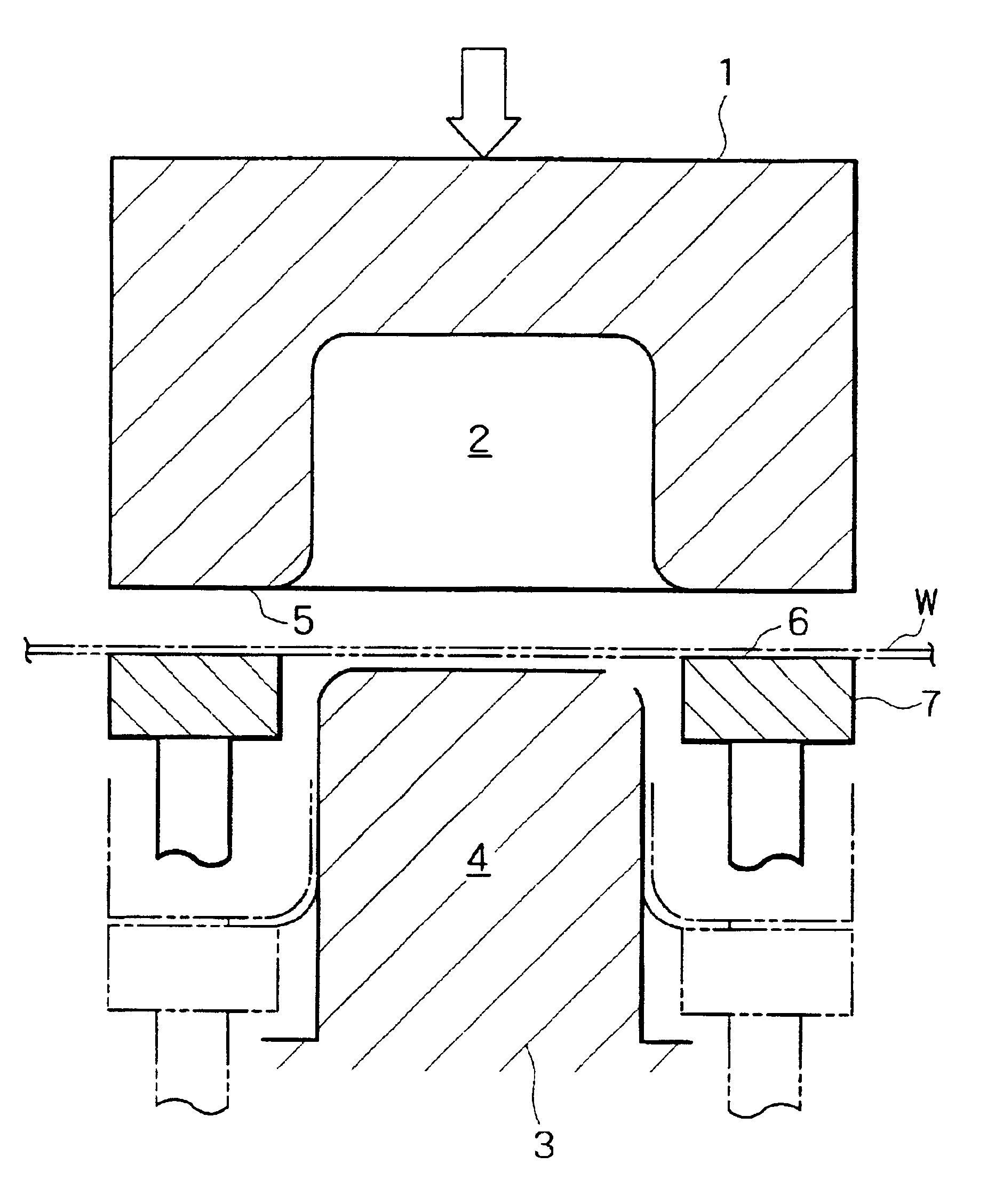
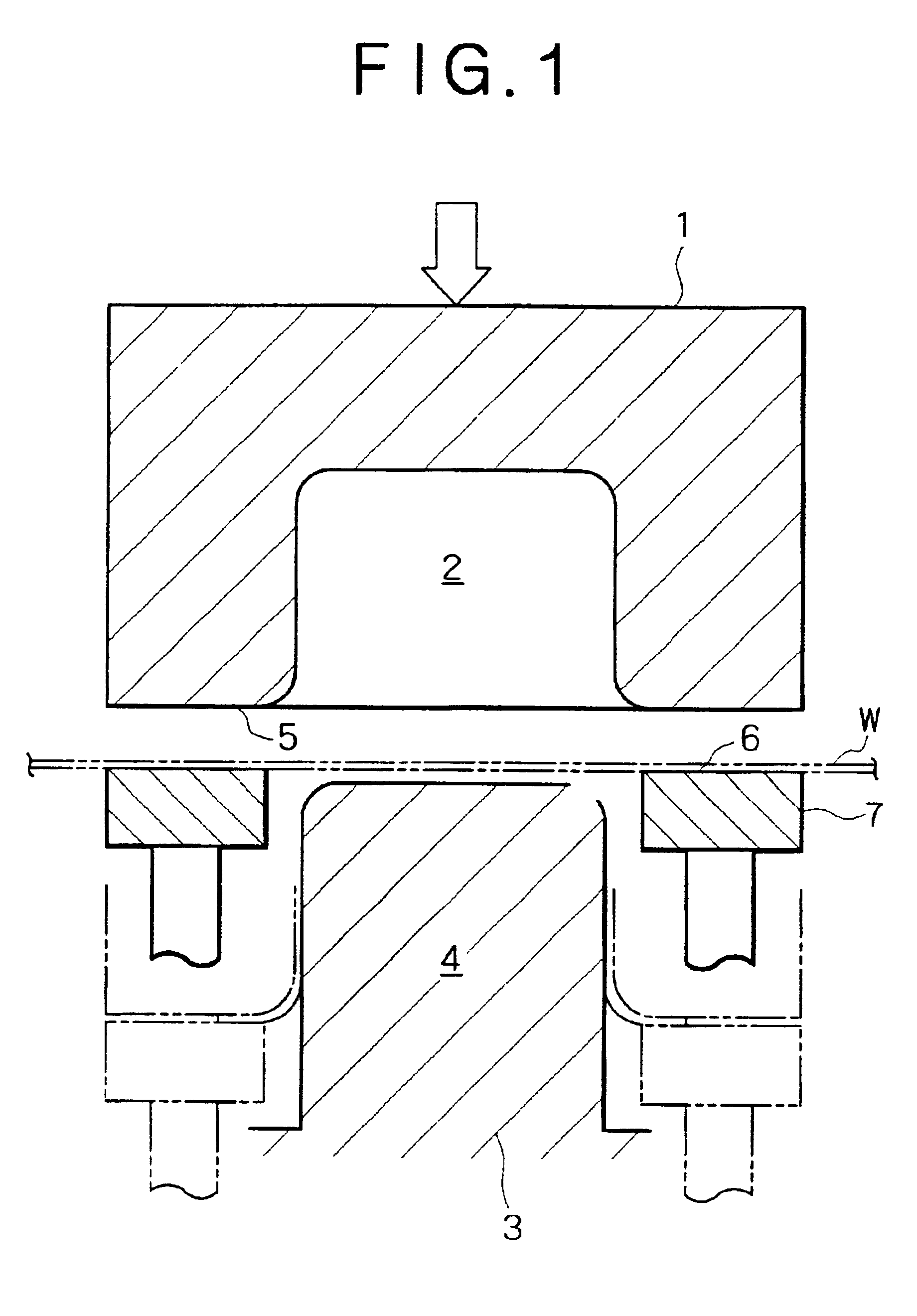
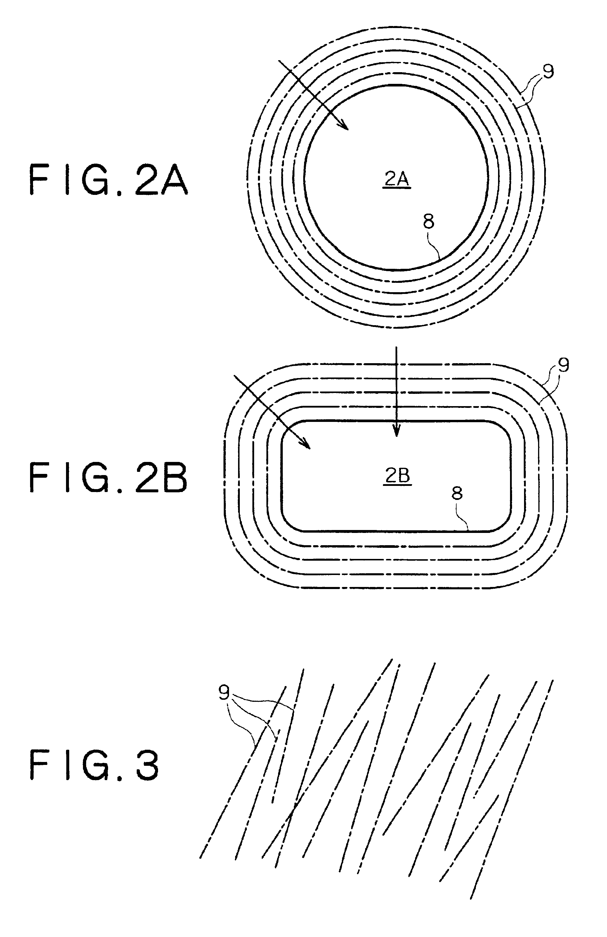
The present invention produces the following effects. The actual contact area between the blank and the first or second blank pressing face is reduced because the blank pressing face is roughened with a plurality of striated projections formed thereon. The reduced contact area causes the blank to experience less sliding resistance. The striated projections are formed in the direction inclined within .+-.25.degree. toward the circumferential direction of the edge of the opening of the concave part. Therefore, the blank comes into discontinuous contact with the blank pressing face. This prevents the blank from being stretched, deformed, and cracked during press forming. The resulting formed product has an accurate thickness.
The roughened face with striated projections should preferably have a surface roughness (Ra) of 0.02-60 .mu.m measured in the direction perpendicular to the circumferential direction of the edge of the opening of the concave part. Such a rough surface is effective in reducing sliding resistance further.
The surface with a number of striated projections 9 should preferably have a surface roughness of 0.02-60 .mu.m (in terms of Ra or the center line average height according to JIS B0601) which is measured in the direction perpendicular to the circumferential direction of the edge of the opening. With a surface roughness smaller than 0.02 .mu.m, the striated projections readily wear out, losing their effect of reducing sliding resistance. With a surface roughness larger than 60 .mu.m, the striated projections rather increase sliding resistance, resulting in a higher production cost. A preferred surface roughness is about 0.1-40 .mu.m in consideration of improved sliding characteristics, durability, and processing cost. Forming the striated projections by cutting is effective in reducing the die production cost. In this case the value of Ra should preferably be 2-30 .mu.m and the height of projection should preferably be about 0.01-0.2 mm for easy working.

Problems solved by technology

Unfortunately, high-strength steel sheets and light metal sheets usually have the disadvantage of being poor in press-formability.
They easily become thin and crack during press-forming, and this prevents their general acceptance.
For example, recent techniques disclosed in Japanese Patent Nos. 2711156, 2815417, and 2857497 are designed to roughen the blank holder surface by intentionally leaving machining marks, thereby reducing the sliding resistance of blanks.
However, nothing is mentioned about the desirable direction of machining marks.

Method used


Image

  • Press die
  • Press die
  • Press die

Examples


example 1

In Example 1 and Comparative Example 1, the slidability of blanks in draw-bending was evaluated in terms of reduction (%) in thickness of the vertical wall of the formed product, in view of the fact that the vertical wall after forming becomes thin variously depending on sliding resistance. The results are shown in FIG. 6. Broken lines in FIG. 6 represent the results in Comparative It is to be noted that reduction in thickness remains constant because the striated projections have no directionality.

It is noted from FIG. 6 that the reduction in thickness decreases in proportion to the decreasing angle between the direction of striated projections and the normal of the edge of the opening of the concave part. It is also noted that the die used in Example 1 gave the slidability and the reduction in thickness which are comparable to or superior to the ordinary press die so long as the striated projections are formed in the direction within .+-.25.degree. from the normal of the edge of ...

example 2

The above-mentioned steel sheet (C) was formed into a U-shaped product by draw-bending by means of a die in which the striated projections on the first and second blank pressing faces varied in surface roughness (Ra) from 0.02 .mu.m to 100 .mu.m (measured in the direction perpendicular to the edge of the opening). The striated projections with Ra smaller than 0.2 .mu.m were formed by using an emery paper (#240-#1000), and the striated projections with Ra larger than 0.2 .mu.m were formed continuously by using a ball end mill (10-30 mm in diameter), with a feed pitch of 1-4 mm. The blanks were examined for slidability in the same way as mentioned above. The results are shown in FIG. 7.

It is noted from FIG. 7 that the reduction in thickness remains almost constant while the surface roughness (Ra) of the striated projections is smaller than 60 .mu.m (to be more strict, smaller than 40 .mu.m), but increases as it exceeds 60 .mu.m. This Example showed that the striated projections produc...


PUM

PropertyMeasurementUnit
Raaaaaaaaaaa
Raaaaaaaaaaa
Raaaaaaaaaaa

Abstract

A press die composed of an upper die having a concave part (with the peripheral surface of the opening of said concave part functioning as a first blank pressing face), a lower die having a convex part (to form the blank into a desired form in cooperation with said concave part), and a blank holder (which has a second blank pressing face), said press die working in such a way that said first blank pressing face and said second blank pressing face hold a blank between them while permitting it to flow into said concave part during pressing, characterized in that at least either of said first blank pressing face and said second blank pressing face has a roughened surface with a plurality of striated projections which are formed in the direction inclined in a range of -25° to +25° (preferably approximately parallel) toward the circumferential direction of the edge of the opening of said concave part.The press die permits the blank to slide easily and hence prevents the blank from decreasing in thickness during press forming.

Description

1. Field of the InventionThe present invention relates to a press die which facilitates the smooth feeding of a blank (a piece of metal sheet cut to a size adequate for forming) at the time of press-forming automotive outer and inner panels.2. Description of the Related ArtsFor improved safety and environmental protection, automobile manufacturers have been attempting to make automotive bodies stronger and lighter by replacing conventional steel sheets with high-strength steel sheets or light-metal sheets (such as aluminum alloy sheets).Unfortunately, high-strength steel sheets and light metal sheets usually have the disadvantage of being poor in press-formability. They easily become thin and crack during press-forming, and this prevents their general acceptance.There have been proposed several techniques for preventing cracking in press-forming. It has been common practice to apply highly-lubricating rust preventing oil to blanks, to form solid lubricating film on blanks, and to us...

Claims


Application Information

Patent Timeline
Patent Type & Authority Patents(United States)
IPC IPC(8): B21D11/18B21D22/02B21D11/00B21D22/00B21D24/04B21D22/20
CPCB21D22/02B21D11/18
Inventor IWAYA, JIRO
Owner KOBE STEEL LTD
Learn More