Heat dissipation apparatus

Inactive Publication Date: 2004-10-12
QUANTA COMPUTER INC
View PDF6 Cites 120 Cited by
  • Summary
  • Abstract
  • Description
  • Claims
  • Application Information

AI Technical Summary

Benefits of technology

One object of the present invention is to provide a heat dissipation apparatus utilizing exterior fresh air for reducing the CPU surface temperature.
Another object of the present invention is to provide a heat dissipation apparatus having a cooling fan whose inlet is isolated from the internal air of the notebook computer to enhance the CPU heat dissipation efficiency.
A further object of the present invention is to utilize multiple heat exchanges for enhancing the total heat dissipation efficiency of the notebook computer.
Therefore, the heat dissipation apparatus according to the present invention can reduce the CPU surface temperature, the internal system temperature, and further enhance the heat dissipation efficiency of the electrical product. The electrical product with the heat dissipation apparatus according to the present invention can save the power consumption and increase the efficiency thereof.

Problems solved by technology

Because the semiconductor manufacture process has highly progressed and functional requirements of the semiconductor are highly intense, the electric circuit layout of the semiconductor becomes more complicated and more sophisticated.
For example, an electric circuit layout of a new generation central processing unit (CPU) is more complicated because the new generation CPU has to provide more powerful functions for users and application software.
The new generation CPU provides powerful functions and performance but more powerful CPU generates more new problems in use.
A serious problem is that the new generation CPU with a complicated circuit has a higher power consumption and thus severely elevates the working temperature of the chips.
The high working temperature can cause instability in a working system, and especially in a small-sized portable device.
Nevertheless, if the working temperature is too high, the performance and stability will decrease and the operation system may even crash, in some extreme situations.
Therefore, the efficiency of the heat dissipation device decreases.
But, even though sucking outside air into the inlet enhances the efficiency of the heat dissipation device of the CPU, the total heat dissipation efficiency of the whole notebook computer still is low.

Method used


Image

  • Heat dissipation apparatus
  • Heat dissipation apparatus
  • Heat dissipation apparatus

Examples


Embodiment Construction

The following description is of the best presently contemplated mode of carrying out the present invention. This description is not to be taken in a limiting sense but is made merely for the purpose of describing the general principles of the invention. The scope of the invention should be determined by referencing the appended claims.

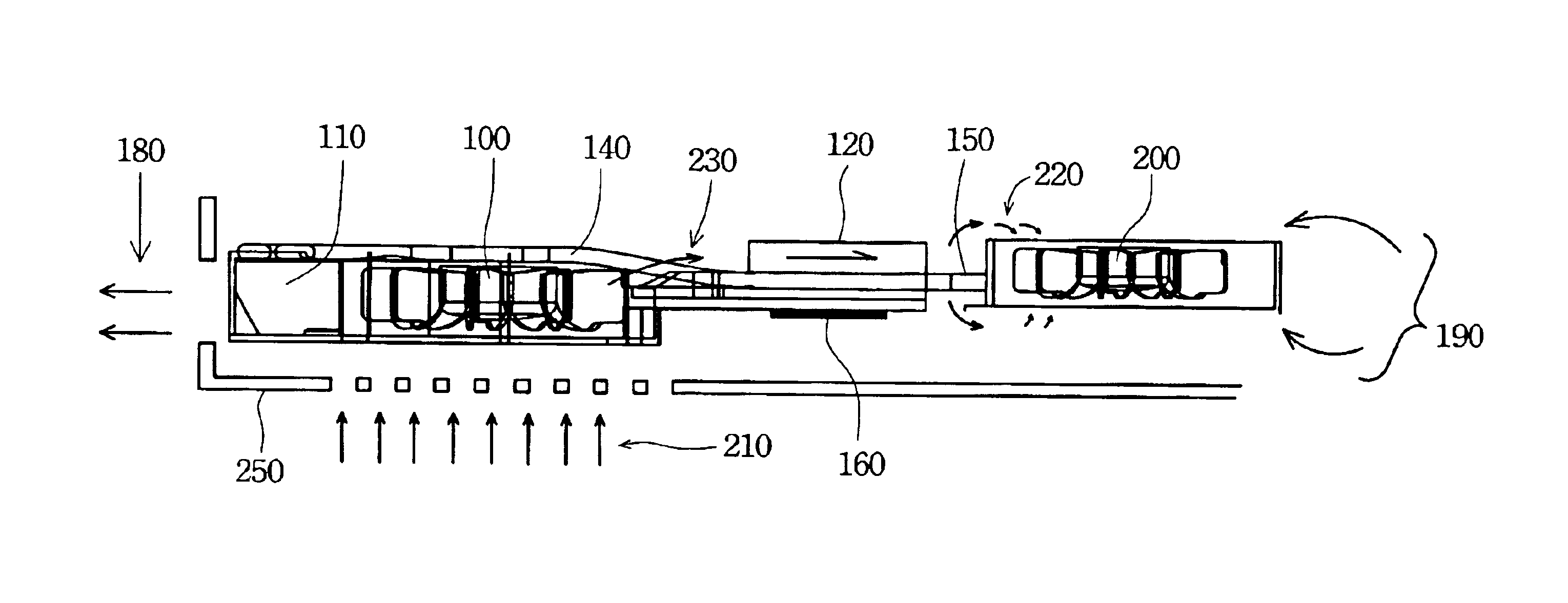
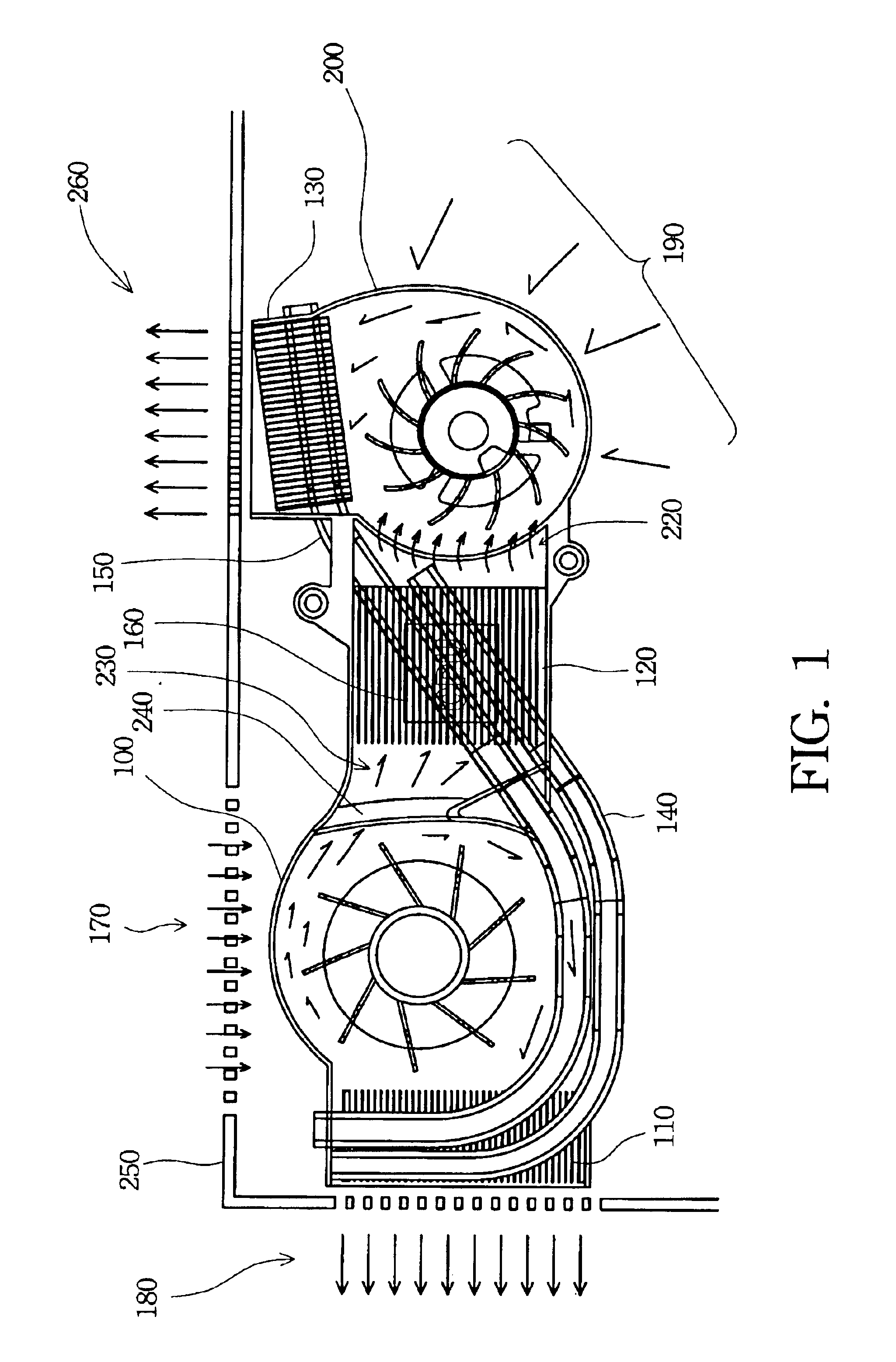
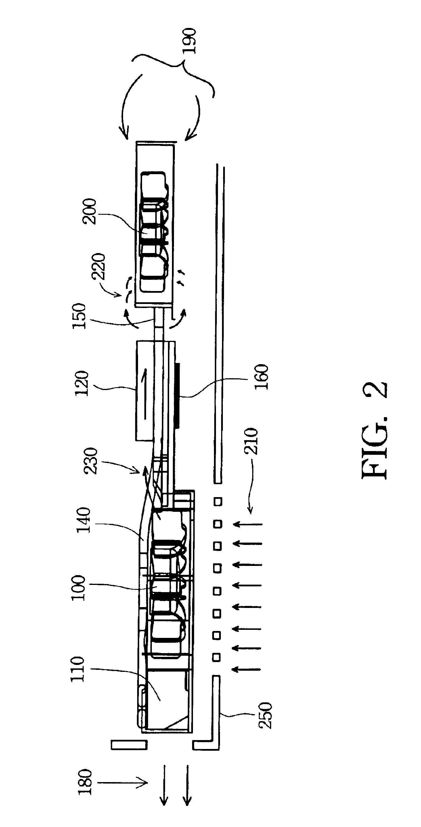
FIG. 1 is a schematic top view of a preferred embodiment of a heat dissipation apparatus according to the present invention. FIG. 2 is a schematic side view of the preferred embodiment of FIG. 1. The heat dissipation apparatus according to the present invention includes a first fan 100, a second fan 200, a first heat dissipation fin 110, a second heat dissipation fin 120, and a third heat dissipation fin 130. A heat impedance is closely linked with a CPU surface temperature, T.sub.CPU, an ambient temperature, T.sub.AMB, and an internal system temperature, T.sub.SYS. The relationship between them is described by the following equation:

where W is the pow...


PUM


Abstract

A heat dissipation apparatus is described. The heat dissipation apparatus is used in an electrical product, and especially in a notebook computer. The heat dissipation apparatus has two cooling fans, at least one heat pipe, and at least two heat dissipation fins. The first fan sucks cooling air from outside of the electrical product. The heat pipe coupling with a heat source transfers heat generated by the heat source to the heat dissipation fins. The first heat dissipation fin and the first fan remove part of the heat out of the electrical product. The second heat dissipation fin further connects with the heat source and the heat pipe to utilize the second fan to remove part of the heat exhausted by the first fan from the electrical product. The heat dissipation apparatus further comprises a third heat dissipation fin and a second heat pipe. The second heat pipe efficiently transfers the heat to each of the heat dissipation fins. The third heat dissipation fin is positioned in an outlet of the second fan to exchange heat again and thus enhance the heat dissipation efficiency.

Description

FIELD OF THE INVENTIONThe present invention relates to a heat dissipation apparatus and especially to enhancing efficiency of the heat dissipation apparatus for a notebook computer.BACKGROUND OF THE INVENTIONInformation technology and the computer industry are highly developed now. Portable electronic devices, such as a notebook computer, are widely used. Due to weight and practical requirements, portable devices tend to be lighter, thinner, shorter or smaller. The notebook computer is a successful product because the notebook computer with powerful calculation capability deals with a great amount of digital data.Because the semiconductor manufacture process has highly progressed and functional requirements of the semiconductor are highly intense, the electric circuit layout of the semiconductor becomes more complicated and more sophisticated. For example, an electric circuit layout of a new generation central processing unit (CPU) is more complicated because the new generation CPU ...

Claims


Application Information

Patent Timeline
IPC IPC(8): H05K7/20
CPCH05K7/202G06F1/203F28D15/0266
Inventor LAI, CHIH-HSI
Owner QUANTA COMPUTER INC
Why Eureka
Try Eureka