
Dual side cooling structure

Active Publication Date: 2019-09-10
DELTA ELECTRONICS INTL SINGAPORE
View PDF1 Cites 0 Cited by
  • Summary
  • Abstract
  • Description
  • Claims
  • Application Information

AI Technical Summary

Benefits of technology

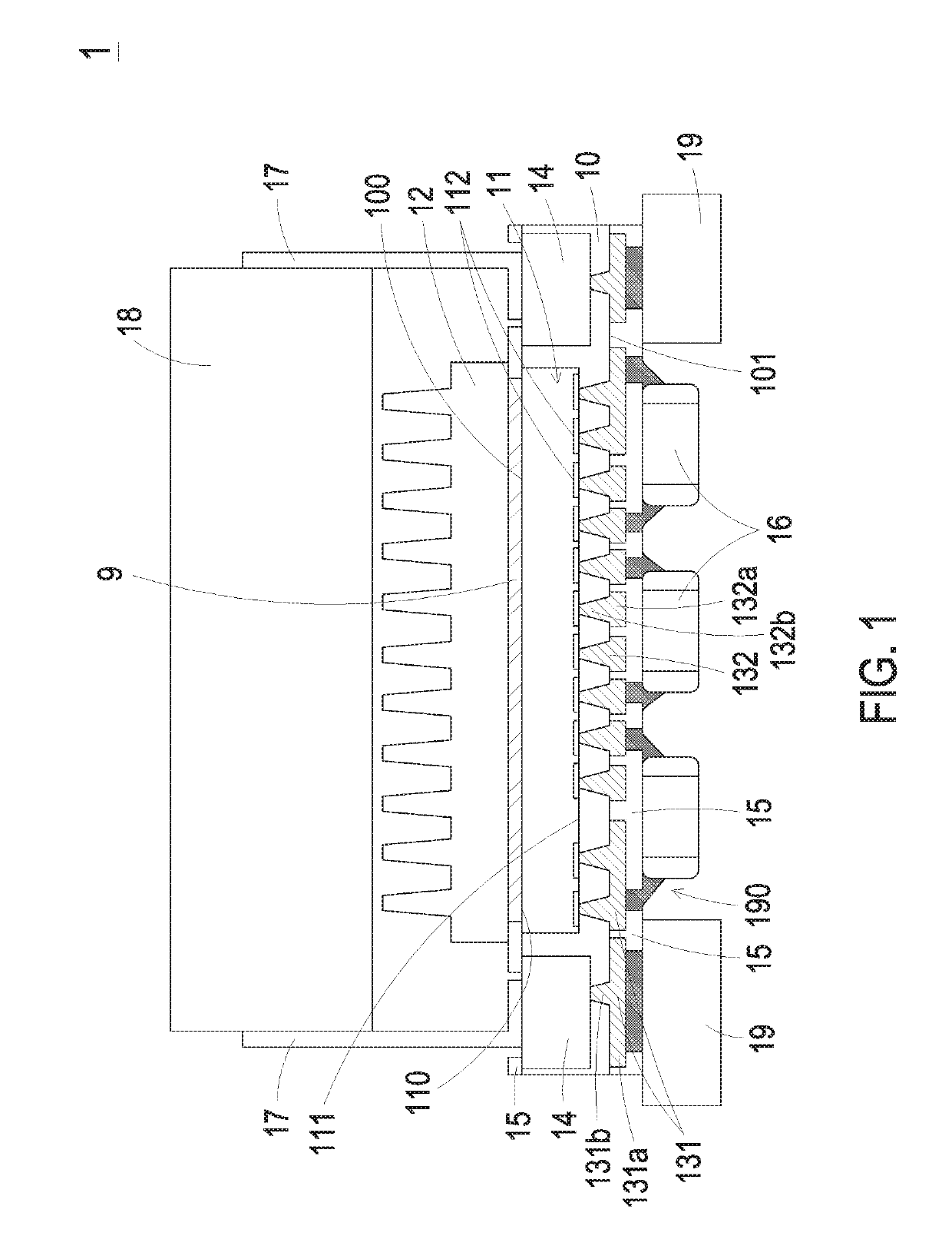
The present invention provides a package structure with an insulation layer, an embedded electronic component, and a heat dissipation device. Specifically, the electronic component has its first surface in direct contact with the heat dissipation device, which improves heat dissipation efficiency. Furthermore, an inductor is placed on top of the heat dissipation device, resulting in a more compact package structure.

Problems solved by technology

However, the conventional package structure of the power module often has bad heat dissipating efficiency when the electronic component embedded within an insulation layer of the conventional package structure of the power module generates a large of heat during working.

Method used


Image

  • Dual side cooling structure
  • Dual side cooling structure
  • Dual side cooling structure

Examples


Embodiment Construction

[0010]The present invention will now be described more specifically with reference to the following embodiments. It is to be noted that the following descriptions of preferred embodiments of this invention are presented herein for purpose of illustration and description only. It is not intended to be exhaustive or to be limited to the precise form disclosed.

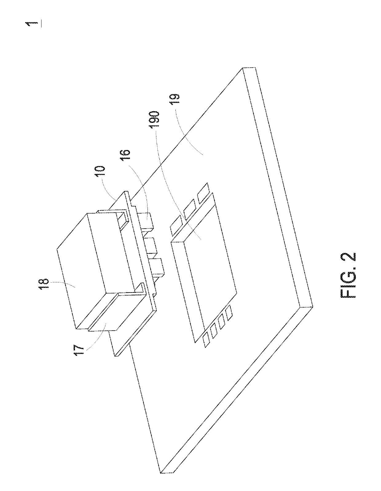
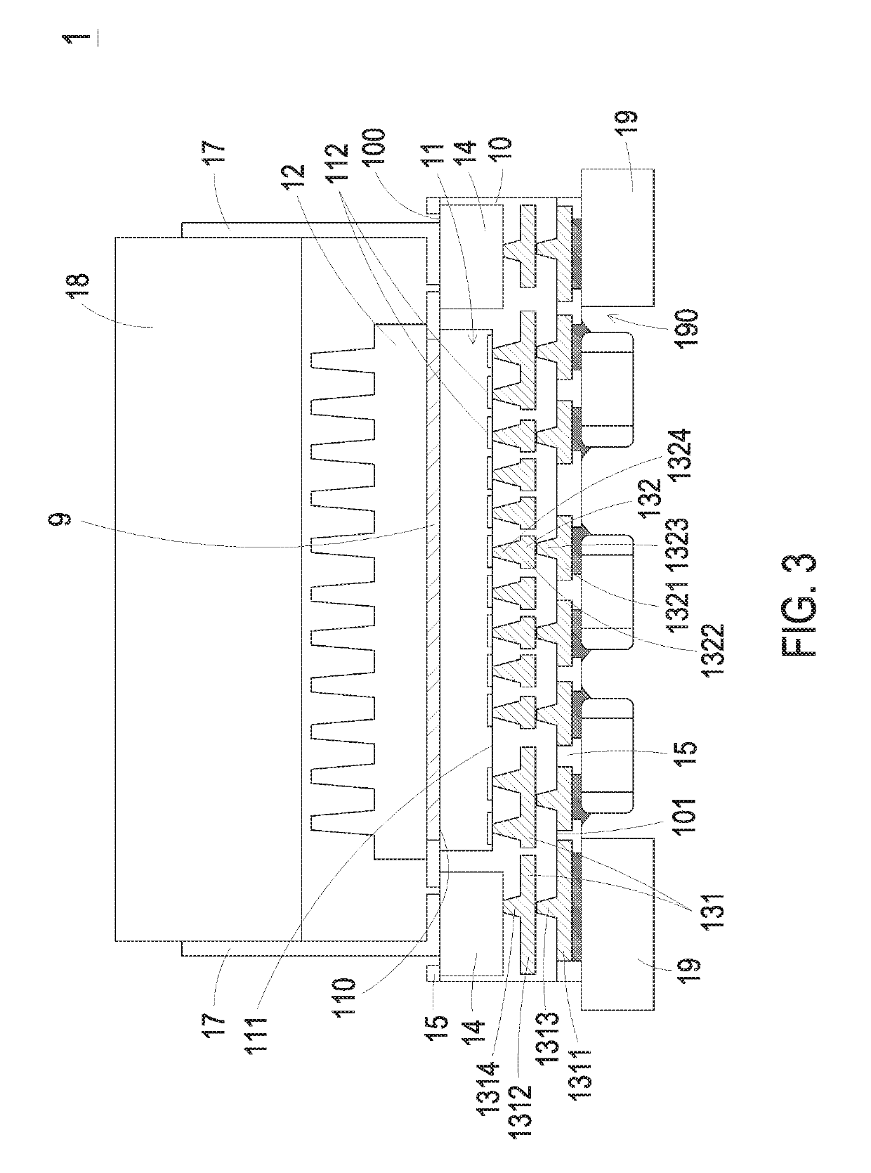
[0011]FIG. 1 is a schematic cross-sectional view illustrating a package structure according to a first embodiment of the present invention. FIG. 2 is a schematic exploded view illustrating the package structure of FIG. 1. As shown in FIGS. 1 and 2, the package structure 1 (hereinafter also referred to as dual side cooling structure) comprises an insulation layer 10, an electronic component 11, a heat dissipation device 12, at least one first re-distribution block 131, and at least one thermal conduction structure 14. The insulation layer 10 can be made of any appropriate insulation material with high thermal conductivity.

[0012]Th...


PUM


Abstract

A package structure includes an insulation layer, an electronic component, at least one thermal conduction structure, a first re-distribution block and a heat dissipation device. The electronic component is embedded within the insulation layer, and comprises a first surface exposed from a top surface of the insulation layer, a second surface and plural conducting terminals formed on the second surface. The at least one thermal conduction structure is embedded within the insulation layer and partially exposed from the top surface of the insulation layer. One part of the first re-distribution block is disposed on a bottom surface of the insulation layer, and the other part of the first re-distribution block is located in the insulation layer and connected with the at least one thermal conduction structure and at least one of the conducting terminals. The heat dissipation device is mounted onto the first surface of the electronic component.

Description

FIELD OF THE INVENTION[0001]The present invention relates to a package structure, and more particularly to a package structure capable of enhancing the heat dissipating efficiency and achieving compact purposes.BACKGROUND OF THE INVENTION[0002]Recently, the general trends in designing electronic devices are toward small size, light weightiness and easy portability. Moreover, with the increasing development of electronic industries, the internal circuitries of the electronic devices are gradually modularized. In other words, plural electronic components are integrated into a single circuit module. For example, a power module is one of the widely-used circuit modules. An example of the power module includes a DC-to-DC converter, a DC-to-AC converter, an AC-to-DC converter, or the like. After the electronic components (e.g. capacitors, resistors, inductors, transformers, diodes and transistors) are integrated as a power module, the power module may be installed on a motherboard or a sy...

Claims


Application Information

Patent Timeline
IPC IPC(8): H05K1/02H05K3/30H05K3/32H05K1/18H05K3/34
CPCH05K1/185H05K1/0209H05K1/021H05K3/3431H05K3/321H05K3/305H05K1/181H01L23/367H05K1/0203H05K1/184H05K2201/10515H05K2201/10962H05K1/141H01L23/147H01L23/5389H01L2224/04105H01L2224/73267H01L2224/32245
Inventor LIM, BENG BENG
Owner DELTA ELECTRONICS INTL SINGAPORE
Learn More