
Vibration reduction device and vibration detecting device and micro signal processing device for use in vibration reduction device

a technology of vibration reduction device and micro signal processing device, which is applied in the direction of color television details, television system details, television systems, etc., can solve the problems of large variation in output when power is turned on, low-frequency output drift, excessively large output,

Inactive Publication Date: 2004-10-05
NIKON CORP
View PDF2 Cites 36 Cited by
  • Summary
  • Abstract
  • Description
  • Claims
  • Application Information

AI Technical Summary

Problems solved by technology

However, the vibration detecting sensor, especially a vibration sensing gyroscope of piezoelectric type generally used in a camera or the like outputs a remarkably unstable output for several tens to hundreds of milliseconds immediately after power turns on, and generates a low-frequency output drift even after the power turns on.
Such variation in output when power turns on is considerably large as compared with a level of an output signal for the vibration to be originally detected in accordance with the acceleration or the angular velocity, and in some case excessively large.
However, the prior-art vibration detecting device has a first problem with the dynamic range of the vibration to be detected and a detecting resolution.
However, since the output range of the operational amplifier OP2 is limited, the dynamic range of the angular velocity that can be detected is decreased when the resolution per bit of quantization is enhanced.
On the other hand, when priority is given to the resolution per bit of quantization or S / N, the dynamic range of vibration which can be detected is disadvantageously narrowed.
Secondly, a problem is caused by a time constant of the high pass filter.
As a result, it takes so much time as cannot be ignored until the output signal Vout is stabilized.
The time elapsed until the offset error can be ignored was intolerably large in a field to which the vibration detecting device is applied, especially in the camera using the silver salt film.
However, since this countermeasure for reducing the offset error is not effective for all the amplitude waveforms, and the offset error surely occurs.
The circuit related to the reference voltage is difficult to design, which increases the cost.
However, when shooting immediately after power turns on, even two seconds cannot be secured.
Since the phase delay causes an error in the vibration reduction control, the phase delay is desirably close to zero.
Immediately after an excessively large vibration occurs, a usual vibration reduction cannot be performed.
To prevent the output from being saturated, in the vibration detecting circuit shown in FIG. 28, the offset adjustment is made by a variable resistor R144, but the cost of the offset adjustment cannot be ignored.
However, because no HPF is disposed in the vibration detecting circuit, an error caused by a DC offset component of the circuit itself is amplified.
For this reason, the vibration detecting circuit is difficult to use for detecting the vibration.
If the input signal to the operational amplifier is dispersed, there is a possibility that a signal exceeding its standard range is inputted, even when the operational amplifier is intended to operate within the standard range.
As a result, the selection of the operational amplifier is limited, thereby increasing the cost.
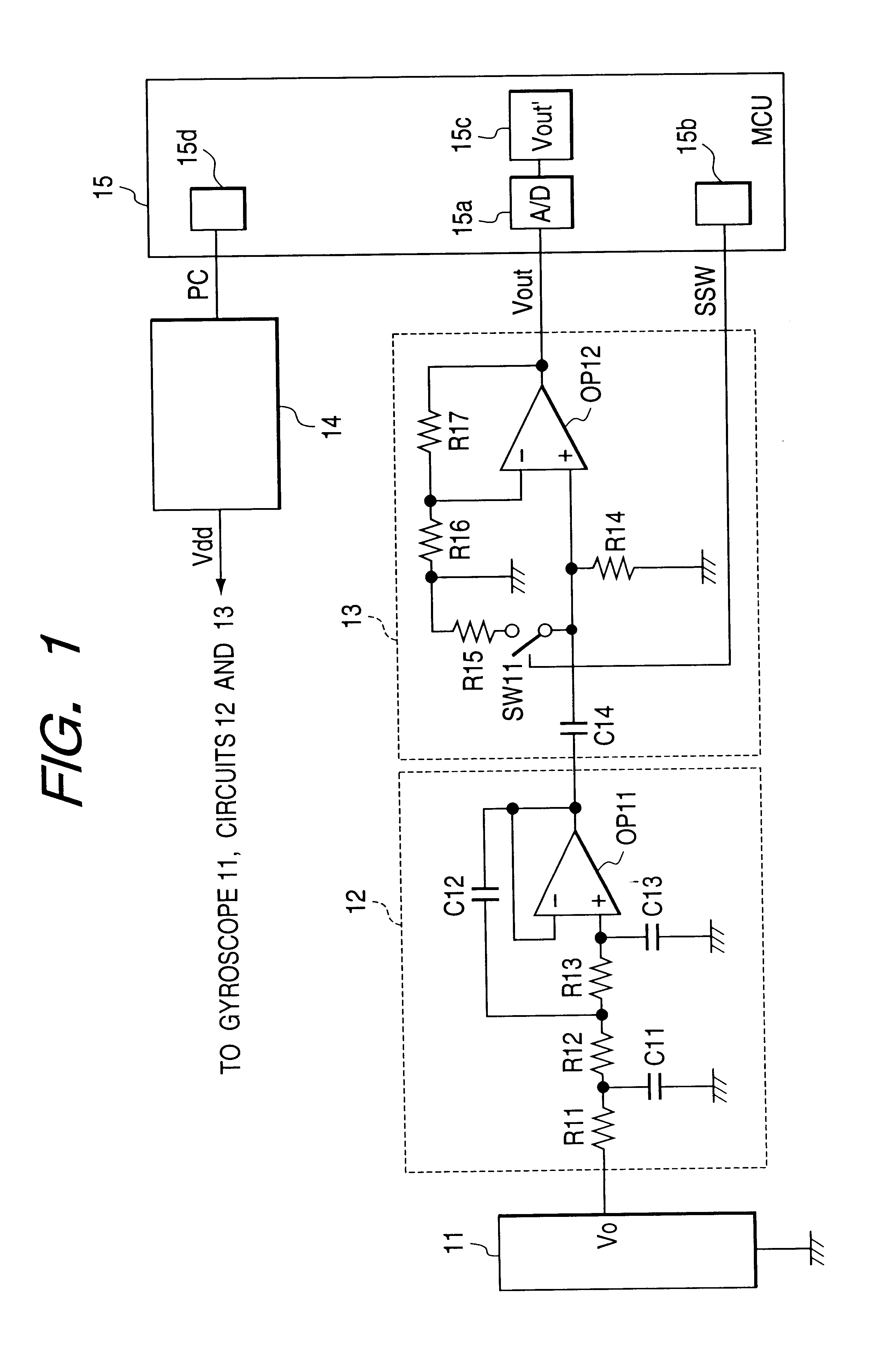
However, in the second embodiment, since no high pass filter is used, the problem caused by the time constant of the high pass filter can be solved.
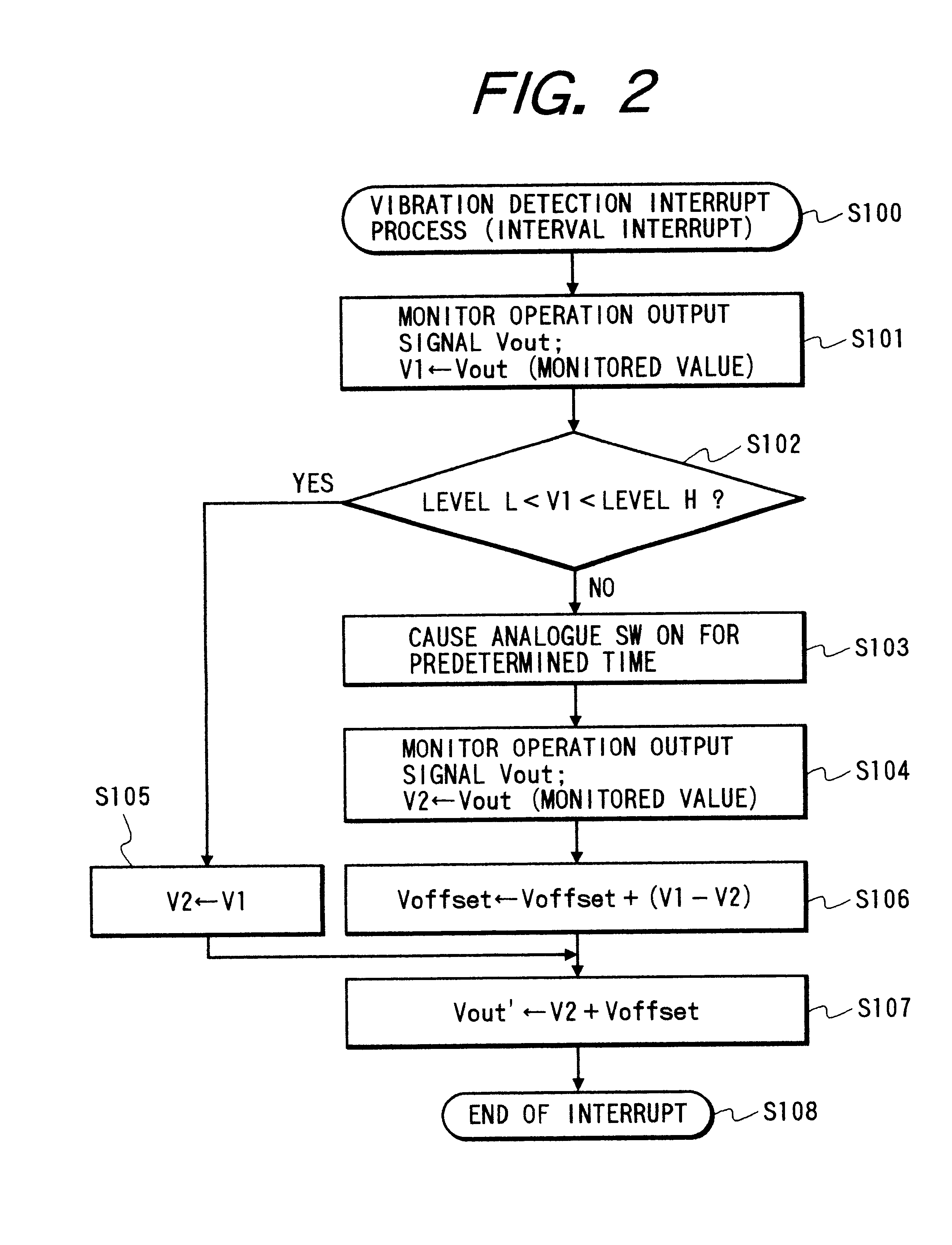
As a result, different from the prior-art vibration detecting device whose output dynamic range is finite, even when the vibration far exceeding the output dynamic range is applied to the circuit shown in FIG. 4, the vibration can be detected through the aforementioned process substantially in real time.
Therefore, to generate the DC voltage value to be added, an expensive D / A converter is unnecessary.
Therefore, an error is caused by the DC offset component.

Method used


Image

  • Vibration reduction device and vibration detecting device and micro signal processing device for use in vibration reduction device
  • Vibration reduction device and vibration detecting device and micro signal processing device for use in vibration reduction device
  • Vibration reduction device and vibration detecting device and micro signal processing device for use in vibration reduction device

Examples


thirteenth embodiment

FIG. 34 is a circuit diagram of a vibration detecting circuit according to a thirteenth embodiment of the invention.

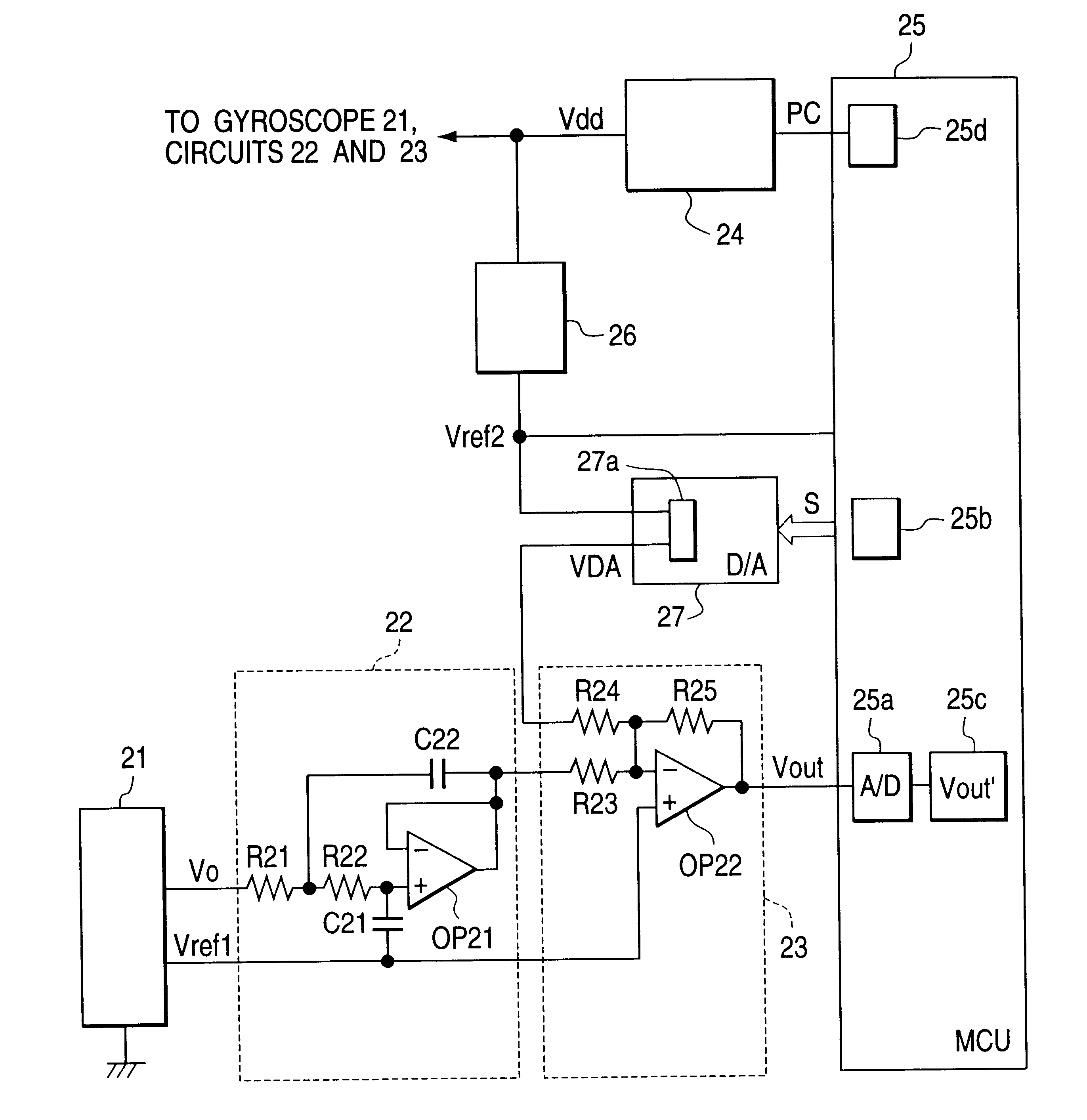
The vibration detecting circuit of the thirteenth embodiment is constituted of the vibration sensing gyroscope 501, the D / A converter 504, a circuit 502 to which an output signal of the vibration sensing gyroscope 501 and an output signal VDA of the D / A converter 504 are transmitted, the A / D converter 503a to which an output signal of the circuit 502 is transmitted and the CPU 503. The circuit 502 is provided with an adder constituted of resistors R501, R502, R503 and R504 and an operational amplifier OP501, an LPF constituted of resistors R501, R502 and R503, capacitors C501 and C502 and an operational amplifier OP501, and the operational amplifier OP501 as an inverting amplifier.

In the vibration detecting circuit, the output signal of the operational amplifier OP501 is AC-fed back via the capacitor C502 for blocking the high-frequency component, and transmitted as a ...

fourteenth embodiment

FIG. 35 is a circuit diagram of a vibration detecting circuit according to a fourteenth embodiment of the invention.

In the vibration detecting circuit of the fourteenth embodiment, the DC offset component can be suppressed. The vibration detecting circuit is constituted of the vibration sensing gyroscope 501 for outputting a micro output signal Vo, the D / A converter 504 for generating a DC voltage (output signal) VDA, the amplifying circuit (adder) 506 for adding an output signal Vo of the vibration sensing gyroscope 501 and the output signal VDA of the D / A converter 504 to amplify, the circuit (LPF) 505 for blocking a high-frequency component of the output signal of the adder 506 to amplify, the A / D converter 503a for receiving an output signal of the LPF 505 and the CPU 503. The constants in the vibration detecting circuit are actually set as follows: resistor R510:47 k.OMEGA., resistor R520:47 k.OMEGA., resistor R530:47 k.OMEGA., resistor R540:4.7 k.OMEGA., resistor R550:470 k.OM...


PUM


Abstract

A vibration detecting device for detecting vibration in a camera, a video movie camera or the like, a vibration reduction device and a micro signal processing circuit. The vibration detecting device comprises a vibration detector for detecting a vibration to output a vibration detecting signal, a calculator for performing a predetermined operation based on the vibration detecting signal, and a controller for determining whether or not an operation output signal of the calculator exceeds a predetermined range. The controller is provided with an operation signal generator for generating an operation signal when the operation output signal exceeds the predetermined range, and the calculator is provided with an initializing portion for returning the operation output signal into the predetermined range based on the operation signal. In the vibration detecting circuit, a DC offset component can be suppressed.

Description

The entire disclosure of Japanese Patent Application Nos. 8-331848, 8-331856, 9-093479, 9-168273, 9-258857 including specifications, claims, drawings and summaries is incorporated herein by reference in their entirety.1. Field of the InventionThe present invention relates to a vibration detecting device for detecting vibration in a camera or an image pickup device for a video movie or the like, and a vibration reduction device for compensating the vibration. The invention also relates to a micro signal processing circuit which can be used in a vibration detecting circuit.2. Related Background ArtFor example, as a prior-art vibration detecting device known is a device which detects acceleration or angular velocity occurring in an apparatus by using an acceleration sensor, an angular velocity sensor or the like. In general, because the acceleration sensor or the angular velocity sensor itself outputs only a slight voltage in relation to a given vibration, an appropriate amplifier is p...

Claims


Application Information

Patent Timeline
IPC IPC(8): H04N5/232
CPCH04N5/23248H04N5/23287H04N5/23258H04N23/68H04N23/6812H04N23/687
Inventor OHISHI, SUEYUKITAGUCHI, FUMIYA
Owner NIKON CORP
Learn More