Depth gauge

a depth gauge and liquid gauging technology, applied in the direction of liquid/fluent solid measurement, level indicators by physical variable measurement, engine lubrication, etc., can solve the problems of false measurement or measurement, prior techniques present certain drawbacks,

Inactive Publication Date: 2004-09-07
MARWAL SYST
View PDF8 Cites 12 Cited by
  • Summary
  • Abstract
  • Description
  • Claims
  • Application Information

AI Technical Summary

Benefits of technology

The height of the housing and the diameter of the opening 12 are selected in such a manner that the reflection of the reference sound wave is sufficient to be detected properly by the portion 92 of the pellet 9. Similarly, the reflection on the reference target portions surrounding the opening 12 when it is desired to measure the depth of the liquid are not detected by the central portion 91. Measurements of liquid depth are thus subject to very little interference.It is possible to further reduce the height of the housing of the system by providing reference obstacles that include sloping reflectors.The fact that the measurement pellet 9 is inside a housing 2 makes it possible for the reference height to be known with greater accuracy than is possible in prior art devices.The housing 2 provides protection for the measurement device. In particular, it enables devices to be provided for protecting electrical connections and solder joints. The system 1 is less sensitive to impacts than are prior art systems.The system 1 has one of the temperature-measuring means mounted in parallel with the surface measuring piezoelectric pellet. These means enable the temperature of the liquid present in the tank to be measured without requiring additional power supply wires.The general advantage of measuring fuel temperature is to enable the engine controller to have a useful value for calculating fuel richness. This improves injection. It is also possible to verify the density of the fuel (which varies as a function of season, for example), and thus to obtain better injection precision.The reference and measurement volumes may be separated by a separator tube extending substantially in register with the separation between the two active portions of the pellet.

Problems solved by technology

Unfortunately, those prior techniques present certain drawbacks.
The reference sound waves directed towards the targets and the sound waves for measuring the surface are sometimes confused, giving rise to false measurements or to measurements mixed with interference.

Method used


Image

  • Depth gauge
  • Depth gauge
  • Depth gauge

Examples


Embodiment Construction

In all of the figures, similar elements are given the same numerical references.

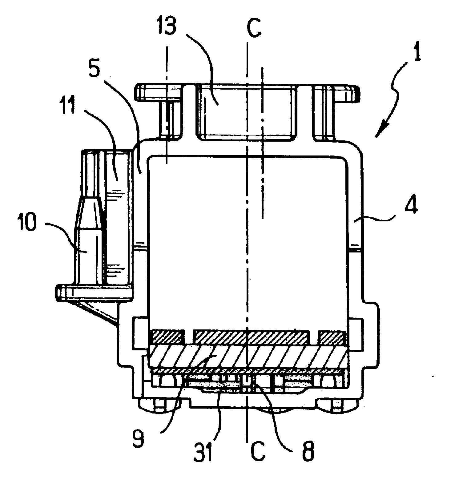
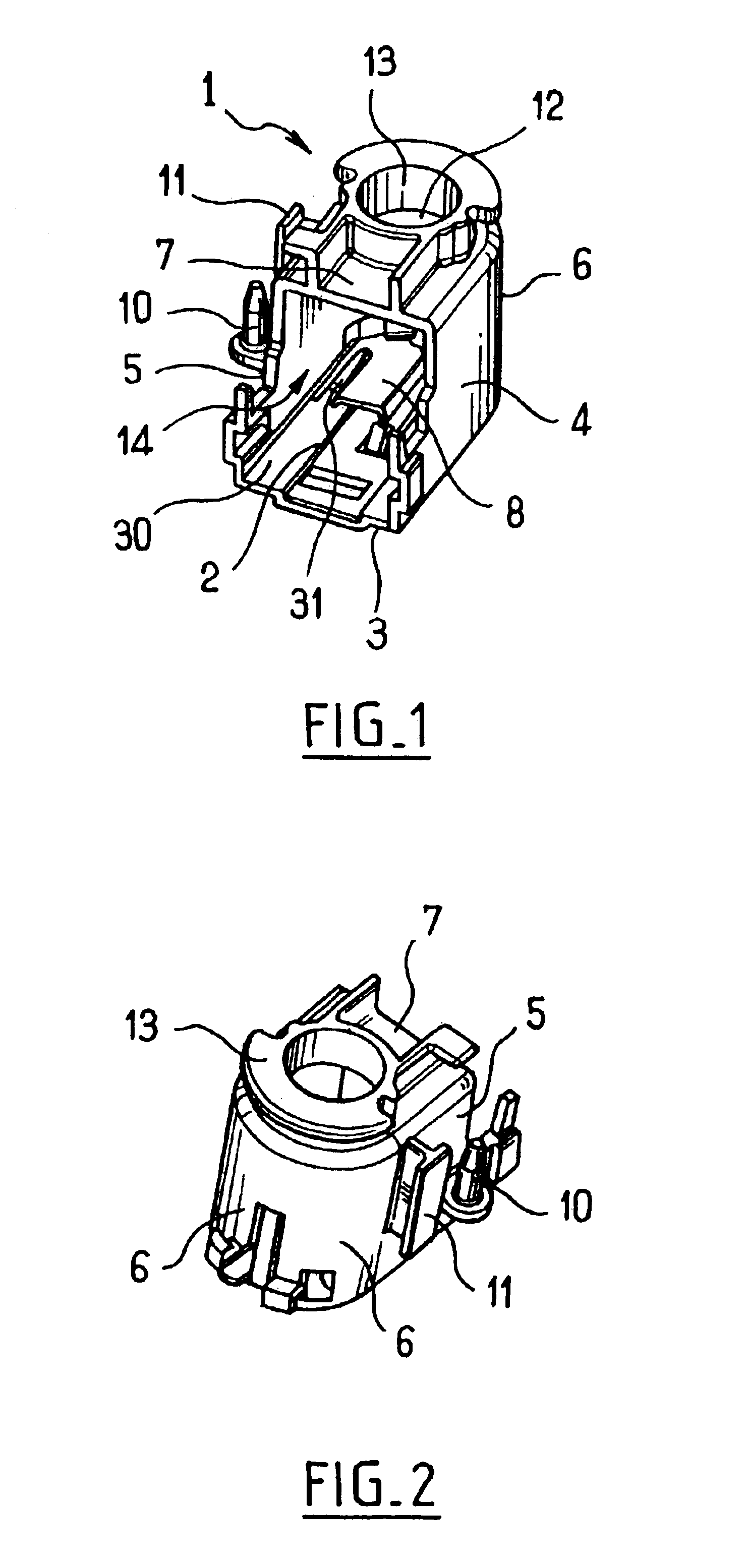
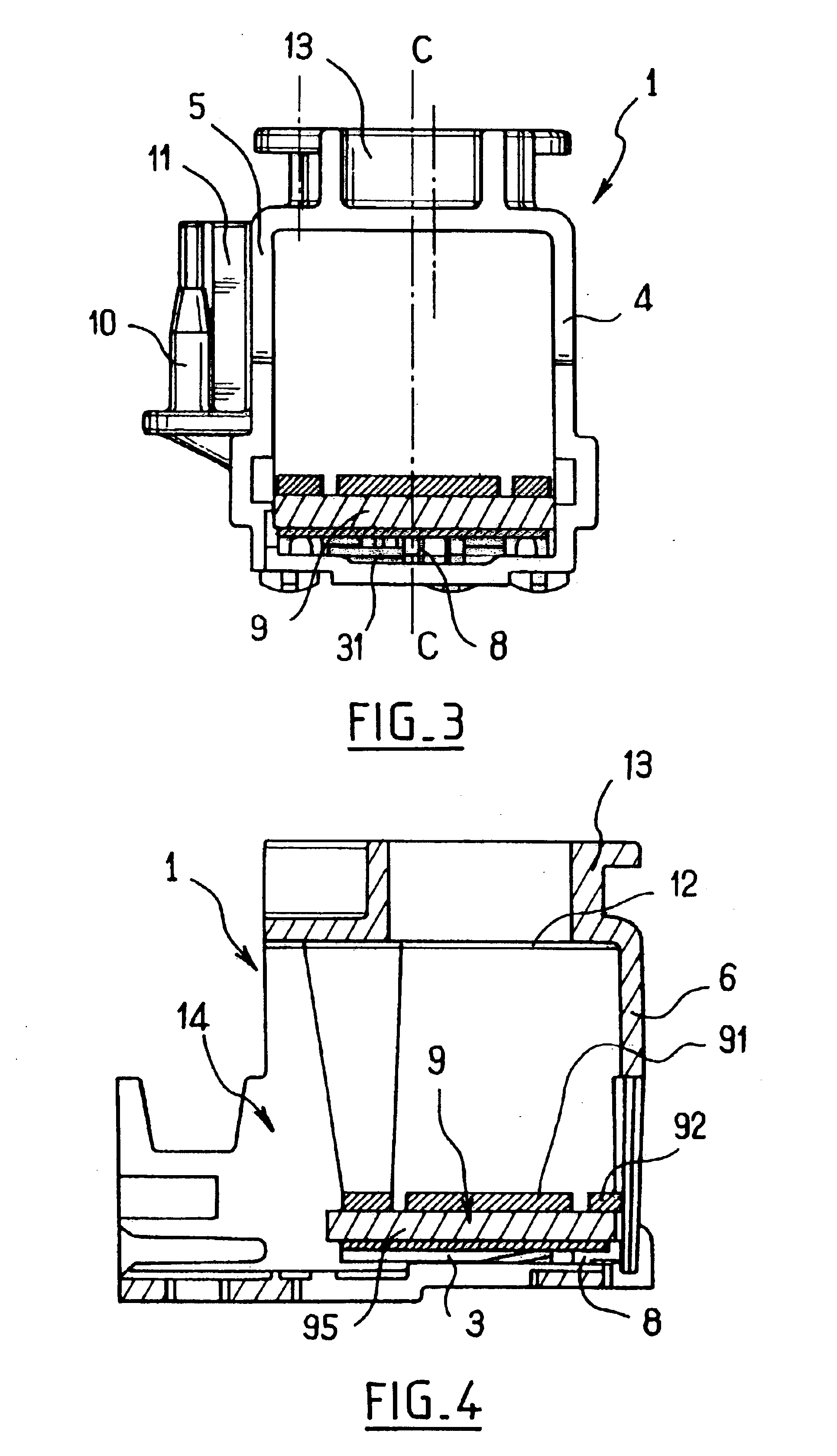
FIG. 1 is an overall view of a gauging device 1 of the invention.

The device 1 comprises a housing 2 of substantially cylindrical shape. The base of the cylinder has an outline that is substantially U-shaped.

The housing 2 has five walls: a bottom wall 3; two plane walls 4 and 5 extending substantially perpendicularly from the bottom wall 3 facing each other and defining the plane sides of the housing 2; a semicylindrical curved wall 6 generated by the bend in the U-shape and interconnecting the plane walls 4 and 5; and a wall 7 closing the top portion of the housing 2 substantially parallel to its bottom wall 3 and including a measurement opening 12.

The bottom wall 3 has a substantially circular location 8 suitable for receiving a piezoelectric measurement pellet 9, itself also substantially circular.

The measurement pellet 9 is described below in the present description and is shown in particular in FIG. ...


PUM


Abstract

The invention provides a piezoelectric liquid gauge system in particular for a motor vehicle fuel tank, the system comprising piezoelectric means suitable for transmitting a sound wave in a liquid and for detecting said wave in order to determine the distance traveled by the wave in the liquid on the basis of the time between transmission and reception, said piezoelectric means comprising two distinct active piezoelectric portions suitable respectively for directing a sound wave towards a reference obstacle and a sound wave towards the surface of the liquid to be gauged, the system being wherein the pellet is contained in a housing suitable for being fixed in position in the tank in which measurement is to be performed, the reference obstacle extending over a face of the housing which faces one of the active portions, said face also having a measurement opening placed facing the other active portion and suitable for allowing the measurement sound waves to pass through.

Description

GENERAL TECHNICAL FIELDThe invention relates to gauging a liquid by means of a piezoelectric pellet.More particularly, the invention relates to a liquid gauging device using a piezoelectric pellet in a housing.STATE OF THE ARTDocument EP 0 182 140 discloses devices for gauging liquid depth by means of piezoelectric pellets.In that technique, the piezoelectric cells are adapted to transmit a sound wave from the bottom of a tank containing a liquid and to detect said wave, e.g. after reflection at the surface of the liquid, in order to determine the depth of the liquid through which the wave has traveled on the basis of the time interval between transmission and reception.Document U.S. Pat. No. 5,095,748 describes in particular a gauging system having targets at known depths to which the sound waves are directed, said targets serving as reference depths for subsequently determining the depth of the liquid.Unfortunately, those prior techniques present certain drawbacks.The reference so...

Claims


Application Information

Patent Timeline
Patent Type & Authority Patents(United States)
IPC IPC(8): G01F23/296
CPCG01F23/2962G01F23/2968
Inventor BENGHEZAL, KARIMVAILLANT, OLIVIERGOUZOU, CHRISTOPHE
Owner MARWAL SYST
Why Eureka
Try Eureka