Method and apparatus for coding moving picture at variable bit rate

a technology of moving pictures and bit rates, applied in electrical apparatus, instruments, computing, etc., can solve problems such as degrading image quality, reducing the generated code quantity, and not performing a real-time process

Inactive Publication Date: 2004-07-13
NEC CORP
View PDF12 Cites 24 Cited by
  • Summary
  • Abstract
  • Description
  • Claims
  • Application Information

AI Technical Summary

Benefits of technology

According to the present invention, it is possible to execute a variable bit rate coding in real time and achieve a high image quality coding.

Problems solved by technology

In particular, in a coding process for the scene that requires a larger quantity of code, it increases the quantization scale and reduces the generated code quantity, thereby causing a disadvantage that it degrades an image quality.
The second example of the prior art is, however, required to execute twice processes, or the preparatory and real coding processes, during coding certain video contents, which consume at least double time period, thereby causing a disadvantage that it can not perform a real time process.
The above described one-pass variable bit rate coding system, however, has a disadvantage that a sequence of coding processes may possibly invite an image quality degradation.
Therefore, the assigned code quantity is increased excessively even though a sufficient image quality is obtained and the codes may be consumed uselessly.
As a result, a sufficient code quantity may not be assigned in such a scene that generates many codes.

Method used


Image

  • Method and apparatus for coding moving picture at variable bit rate
  • Method and apparatus for coding moving picture at variable bit rate
  • Method and apparatus for coding moving picture at variable bit rate

Examples


first embodiment

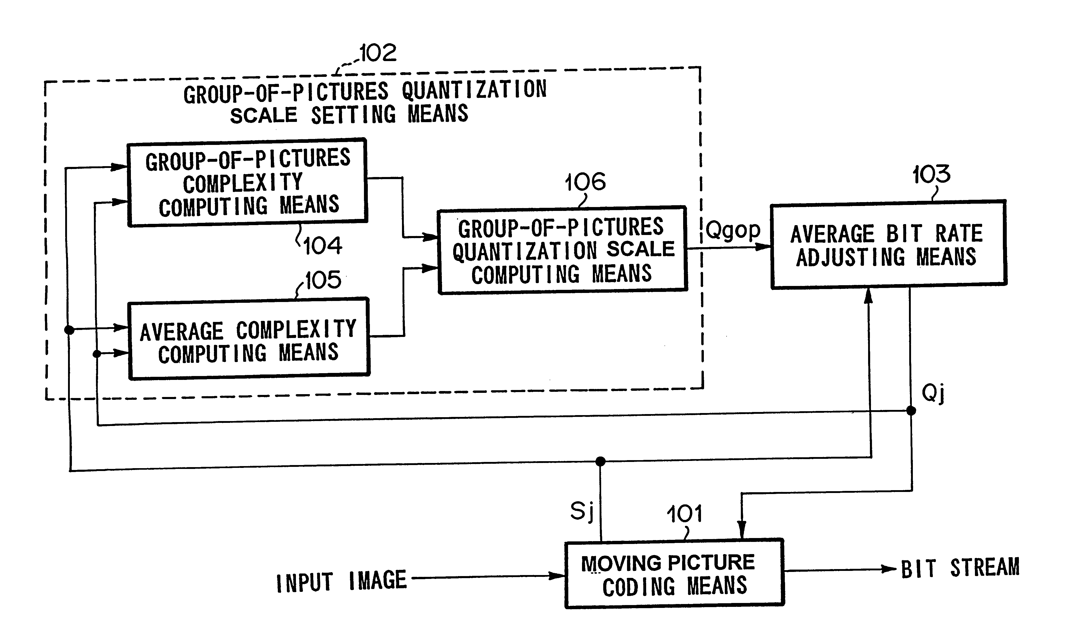
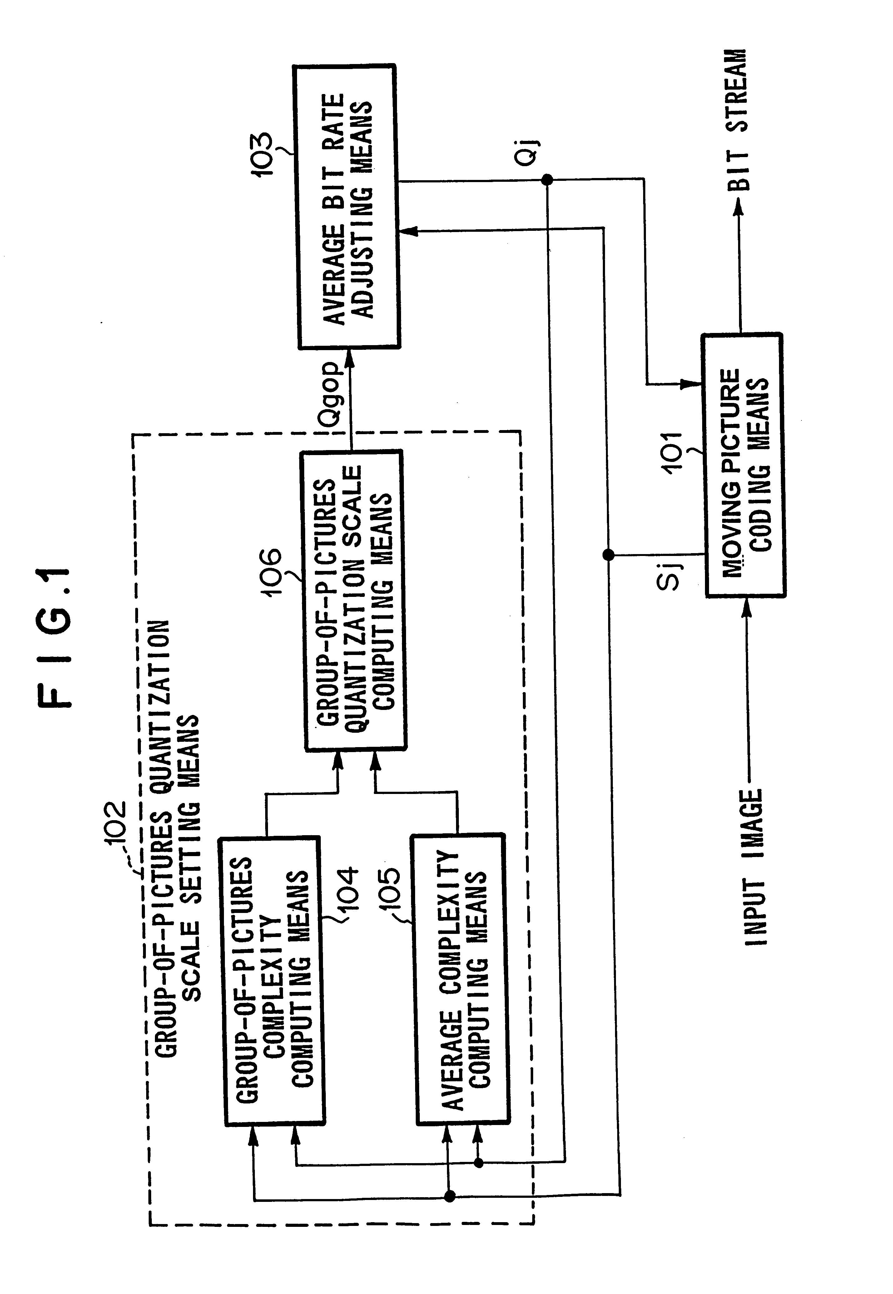
FIG. 1 is a block diagram illustrating a variable bit rate moving picture coding method of the present invention. MPEG-2 (ISO / ICE-13818) system is employed as a coding system in the present invention. The coding system is, however, not limited in MPEG-2 (ISO / ICE-13818) system. Rather, any coding technology can be employed so long as its code quantity is controlled by a quantization scale along with a scalar quantization process. For example, MPEG-1 (ISO / IEC-11172), ITU-T .261 and ITU-T H.263 may also be employed.

The quantization scale given to the moving picture coding means is a given value as a standard for bit rate control. Therefore, it does not prevent an adaptive quantization corresponding to a local position within a picture. Accordingly, a finally given adaptive quantization scale may be different from the quantization scale given to the moving picture coding means as the standard for bit rate control. Any way, in the present invention, the first image coding unit is a group...

sixth embodiment

A sixth embodiment according to the present invention can be configured, although it is not illustrated in the drawings, to include such a means for adjusting the quantization scale output from the average bit rate adjusting means 103 as a maximum excessive code quantity, Dmax, from the average bit rate of the virtual buffer occupancy "vboc", which is set to control the quantization scale. For example, with respect to a parameter, Qreact, which is employed in correction of the quantization scale with the virtual buffer occupation quantity, vboc, it can be determined by subtracting the virtual buffer occupancy "vboc", from the maximum excessive code quantity, Dmax, to compute an available code quantity, (Dmax-vboc). Then selecting the smaller one between, Qreact, and, Dmax-vboc, as the parameter Qreact; Qreact=min (Qreact, Dmax-vboc).

In stead of using the parameter qreact, Qj may be used,

where Qj=Qgop.times.(1+vboc / (Dmax-vboc)); or

Qj=Qgop.times.(Dmax / (Dmax-vboc))


PUM


Abstract

To provide a picture coding method and apparatus capable of achieving a high image quality coding and executing a variable bit rate coding in real time. A moving picture coding means codes input moving picture data with a quantization scale Qj given from an average bit rate adjusting means. Then, the moving picture coding means outputs a code quantity Sj towards a GOP complexity computing means and an average complexity computing means. The GOP complexity is calculated on the basis of quantization scale and code quantity in the coded GOP, while the average complexity is calculated on the basis of quantization scale and code quantity from the beginning to the present. Quantization scale Qgop is calculated on the basis of the GOP complexity and the average complexity. The average bit rate adjusting means modifies Qgop and determines quantization scale Qj in accordance with an excess or shortage of Sj.

Description

1. Technical Field of the InventionThe present invention relates to a method and apparatus for coding moving pictures at a variable bit rate, and more particularly to a method and apparatus for coding moving pictures at a variable bit rate, which can control a code quantity at a variable bit rate in real time.2. Description of the Prior ArtMPEG-2 (ISO-IEC-13818-2) has been typically known as a method of coding moving pictures with a high efficiency in the art. In this method, a picture is divided into blocks each consisting of a group of plural pixels, and each block is subject to the discrete cosine transform (DCT) to transform a signal in a spatial domain into a signal in a frequency domain. Each frequency component obtained from the discrete cosine transform, which is called a "DCT coefficient", is quantized with a predetermined quantization scale, then coded in a variable length by assigning a variable length code to a quantized transform coefficient, and output as a bit stream ...

Claims


Application Information

Patent Timeline
Patent Type & Authority Patents(United States)
IPC IPC(8): G06T9/00H04N19/00H04N19/115H04N19/126H04N19/134H04N19/14H04N19/146H04N19/176H04N19/194H04N19/196H04N19/50H04N19/503H04N19/593H04N19/60
CPCH04N19/115H04N19/61H04N19/124H04N19/14H04N19/177
Inventor YOKOYAMA, YUTAKA
Owner NEC CORP
Why Eureka
Try Eureka