
Sound recording and reproduction systems

a sound recording and reproduction system technology, applied in the direction of stereophonic arrangments, loudspeaker spatial/constructional arrangements, electrical devices, etc., can solve the problems of difficult to give the listener the impression that the virtual sound source is truly external, and the headphone reproduction of binaural material often suffers from in-the-head localisation of certain sound sources

Inactive Publication Date: 2004-07-06
ADAPTIVE AUDIO
View PDF7 Cites 35 Cited by
  • Summary
  • Abstract
  • Description
  • Claims
  • Application Information

AI Technical Summary

Benefits of technology

In accordance with a fourth aspect, the present invention may also be implemented by creating sound recordings that can be subsequently played through a closely-spaced pair of loudspeakers using `conventional` stereo amplifiers, filter means being employed in creating the sound recordings, thereby avoiding the need to provide a filter means at the input to the speakers.

Problems solved by technology

However, headphone reproduction of binaural material often suffers from `in-the-head` localisation of certain sound sources, and poor localisation of frontal and rear sources.
It is generally very difficult to give the listener the impression that the virtual sound source is truly external, i.e. `outside the head`.
A fundamental problem that one faces when using such a loudspeaker arrangement is that convincing virtual images are only experienced within a very confined spatial region or `bubble` surrounding the listener's head.
Thus, virtual source imaging using two widely spaced loudspeakers is not very robust with respect to head movement.

Method used


Image

  • Sound recording and reproduction systems
  • Sound recording and reproduction systems
  • Sound recording and reproduction systems

Examples


Embodiment Construction

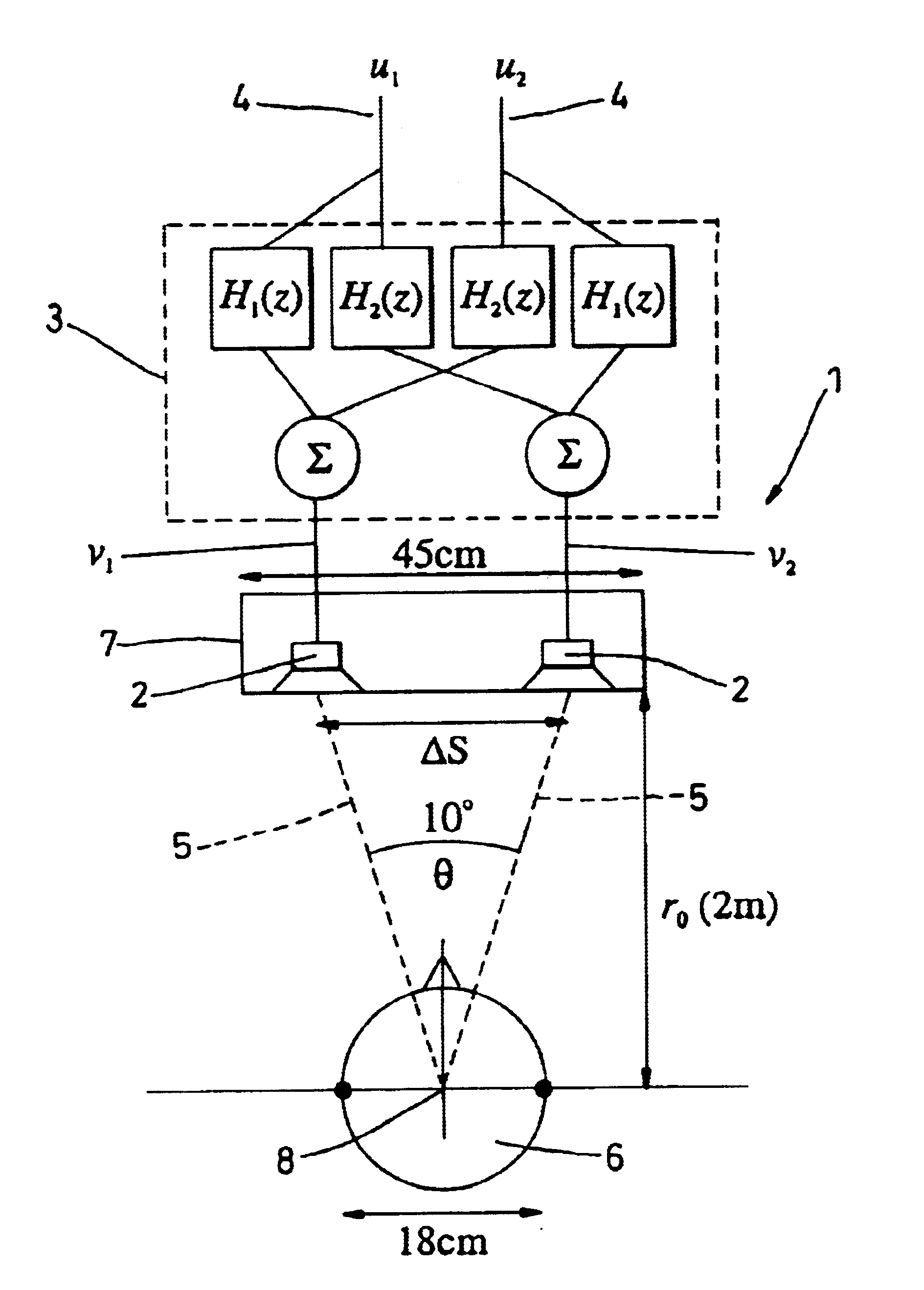
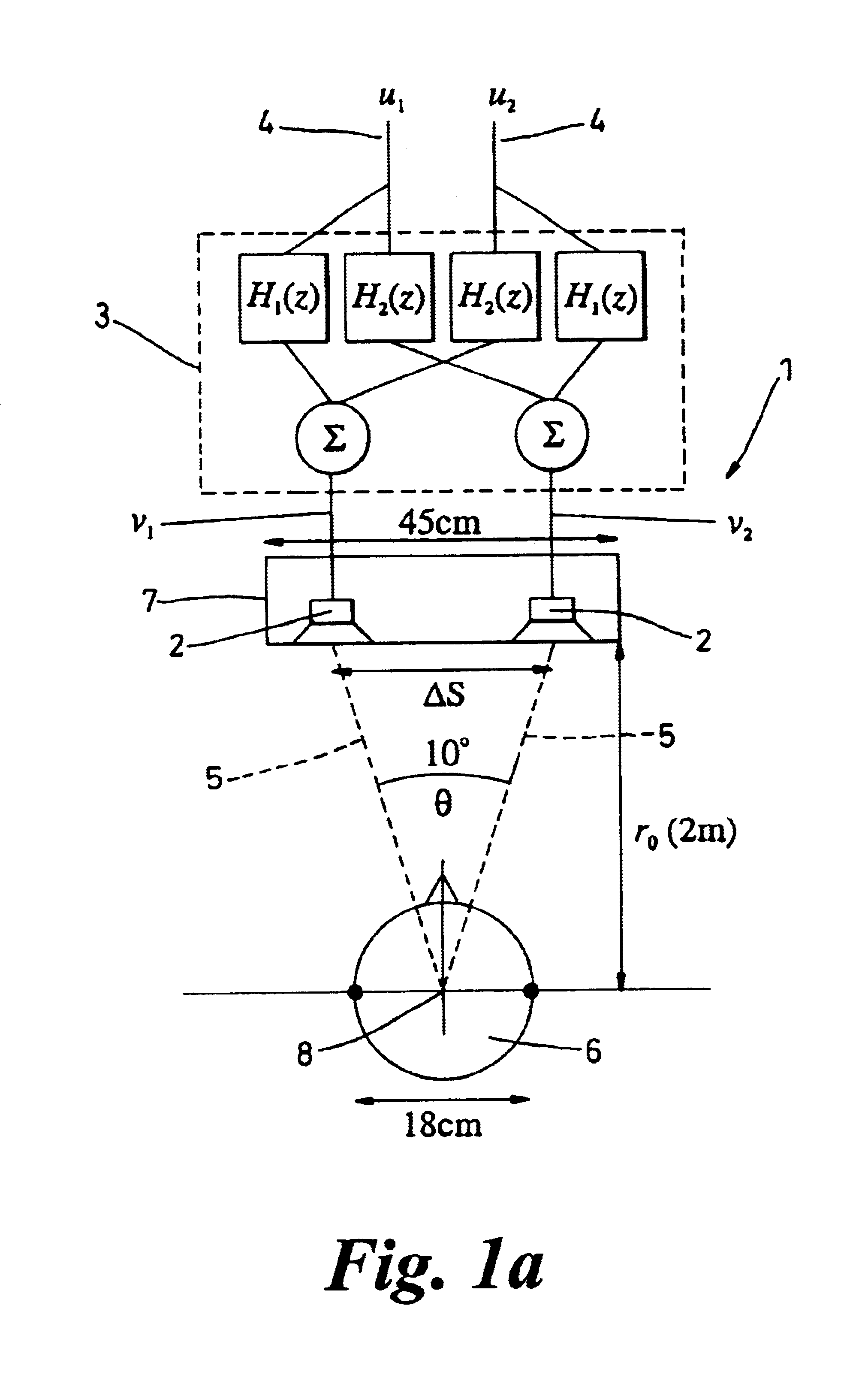
With reference to FIG. 1(a), a sound reproduction system 1 which provides virtual source imaging, comprises loudspeaker means in the form of a pair of loudspeakers 2, and loudspeaker drive means 3 for driving the loudspeakers 2 in response to output signals from a plurality of sound channels 4.

The loudspeakers 2 comprise a closely-spaced pair of loudspeakers, the radiated outputs 5 of which are directed towards a listener 6. The loudspeakers 2 are arranged so that they to define, with the listener 6, a convergent included angle .theta. of between 6.degree. and 20.degree. inclusive.

In this example, the included angle .theta. is substantially, or about, 10.degree..

The loudspeakers 2 are disposed side by side in a contiguous manner within a single cabinet 7. The outputs 5 of the loudspeakers 2 converge at a point 8 between 0.2 meters and 4.0 meters (distance r.sub.0) from the loudspeaker. In this example, point 8 is about 2.0 meters from the loudspeakers 2.

The distance .DELTA.S (span) ...


PUM


Abstract

A method of recording sound for reproduction by a plurality of loudspeakers, or for processing sound for reproduction by a plurality of loudspeakers, is described in which some of the reproduced sound appears to a listener to emmanate from a virtual source which is spaced from the loudspeakers. A filter means (H) is used either in creating the recording, or in processing the recorded signals for supply to loudspeakers, the filter means (H) being created in a filter design step in which: a) a technique is employed to minimise error between the signals (w) reproduced at the intended position of a listener on playing the recording through the loudspeakers, and desired signals (d) at the intended position, wherein: b) said desired signals (d) to be produced at the listener are defined by signals (or an estimate of the signals) that would be produced at the ears of (or in the region of) the listener in said intended position by a source at the desired position of the virtual source. A least squares technique may be employed to minimise the time averaged error between signal reproduced at the intended position of a listener and the desired signal, or it may be applied to the frequency domain.

Description

BACKGROUND TO THE INVENTIONThis invention relates to sound recording and reproduction systems, and is particularly concerned with stereo sound reproduction systems wherein at least two loudspeakers are employed.It is possible to give a listener the impression that there is a sound source, referred to as a virtual sound source, at a given position in space provided that the sound pressures that are reproduced at the listener's ears are the same as the sound pressures that would have been produced at the listener's ears by a real source at the desired position of the virtual source. This attempt to deceive the human hearing can be implemented by using either headphones or loudspeakers. Both methods have their advantages and drawbacks.Using headphones, no processing of the desired signals is necessary irrespective of the acoustic environment in which they are used. However, headphone reproduction of binaural material often suffers from `in-the-head` localisation of certain sound source...

Claims


Application Information

Patent Timeline
IPC IPC(8): H04S1/00H04R5/02
CPCH04R5/02H04S1/002H04S7/302H04R2205/022H04S2420/01
Inventor NELSON, PHILIP ARTHURKIRKEBY, OLEHAMADA, HAREO
Owner ADAPTIVE AUDIO
Learn More