
Methodology and graphical user interface for building logic synthesis command scripts using micro-templates

a micro-template and command script technology, applied in the field of micro-template graphical user interface (gui) and methodology, can solve the problems of increasing the complexity of the devices employing them, the difficulty of designing these ics, and the smaller transistors

Inactive Publication Date: 2004-02-24
GLOBALFOUNDRIES INC
View PDF18 Cites 89 Cited by
  • Summary
  • Abstract
  • Description
  • Claims
  • Application Information

AI Technical Summary

Benefits of technology

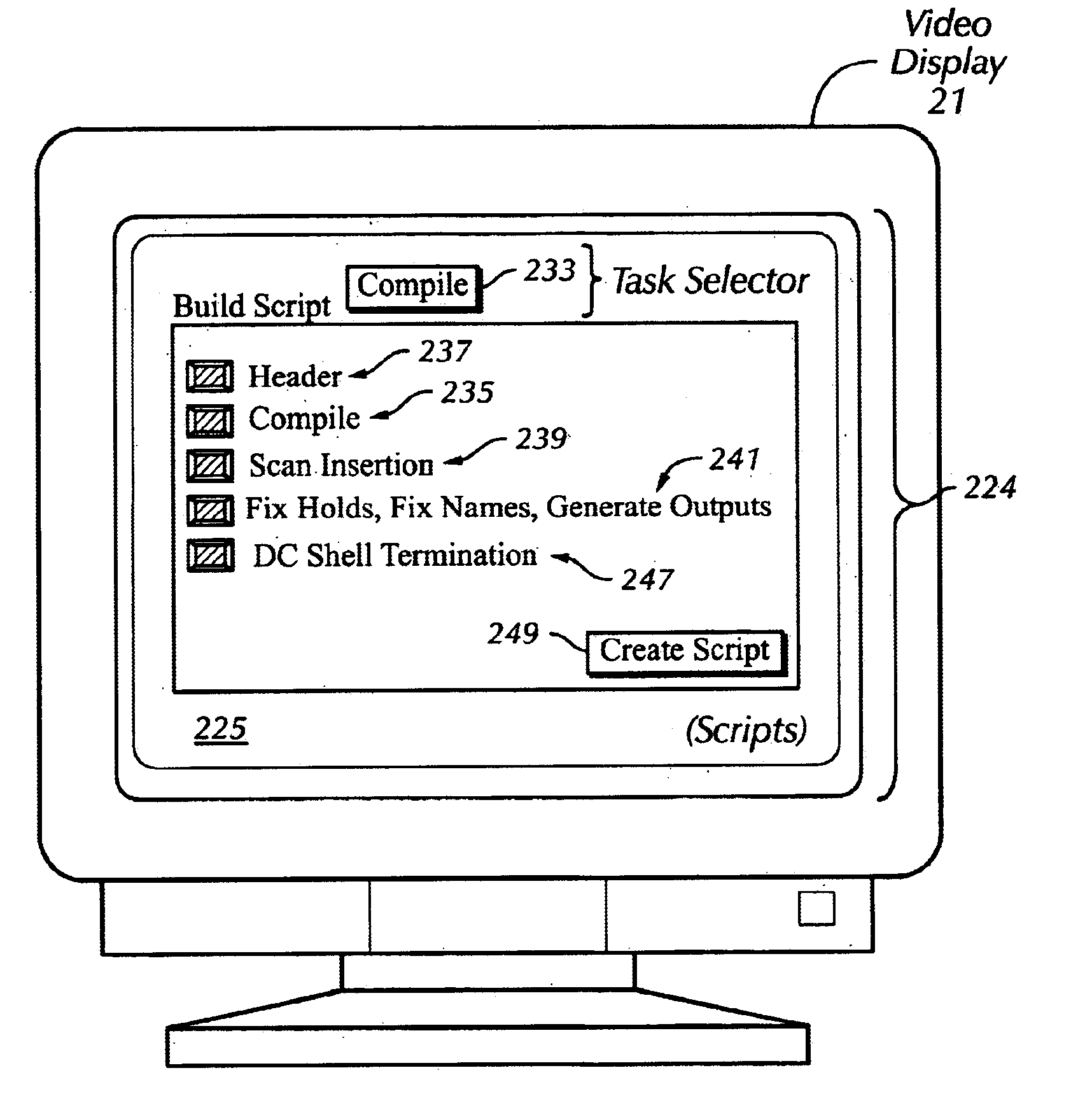
A disclosed GUI is a build script graphical user interface to selectively enable and disable micro-templates. The build script GUI includes a Create script option to build a logic synthesis command script corresponding to enabled micro-templates. In the past, to debug logic synthesis whether through manual or script-based commands, it was necessary to resynthesize for virtually all synthesis operations. The time to do so was prohibitive. In accordance with the present invention, by using the build script GUI to enable only the synthesis operations of debug interest, synthesis time may be significantly reduced.

Problems solved by technology

With astonishing regularity over the past several decades, transistors have become smaller and the devices that employ them have become more complex.
The job of designing these ICs has also grown correspondingly more difficult.
Logic synthesis command scripts generate extremely long run times due to their complex nature.
As microprocessors, microcontrollers, and dedicated integrated circuits grow larger and more complex, the EDA tools and the compilers that design these circuits become more and more taxed to perform their tasks.
The time to do so was prohibitive.

Method used


Image

  • Methodology and graphical user interface for building logic synthesis command scripts using micro-templates
  • Methodology and graphical user interface for building logic synthesis command scripts using micro-templates
  • Methodology and graphical user interface for building logic synthesis command scripts using micro-templates

Examples


Embodiment Construction

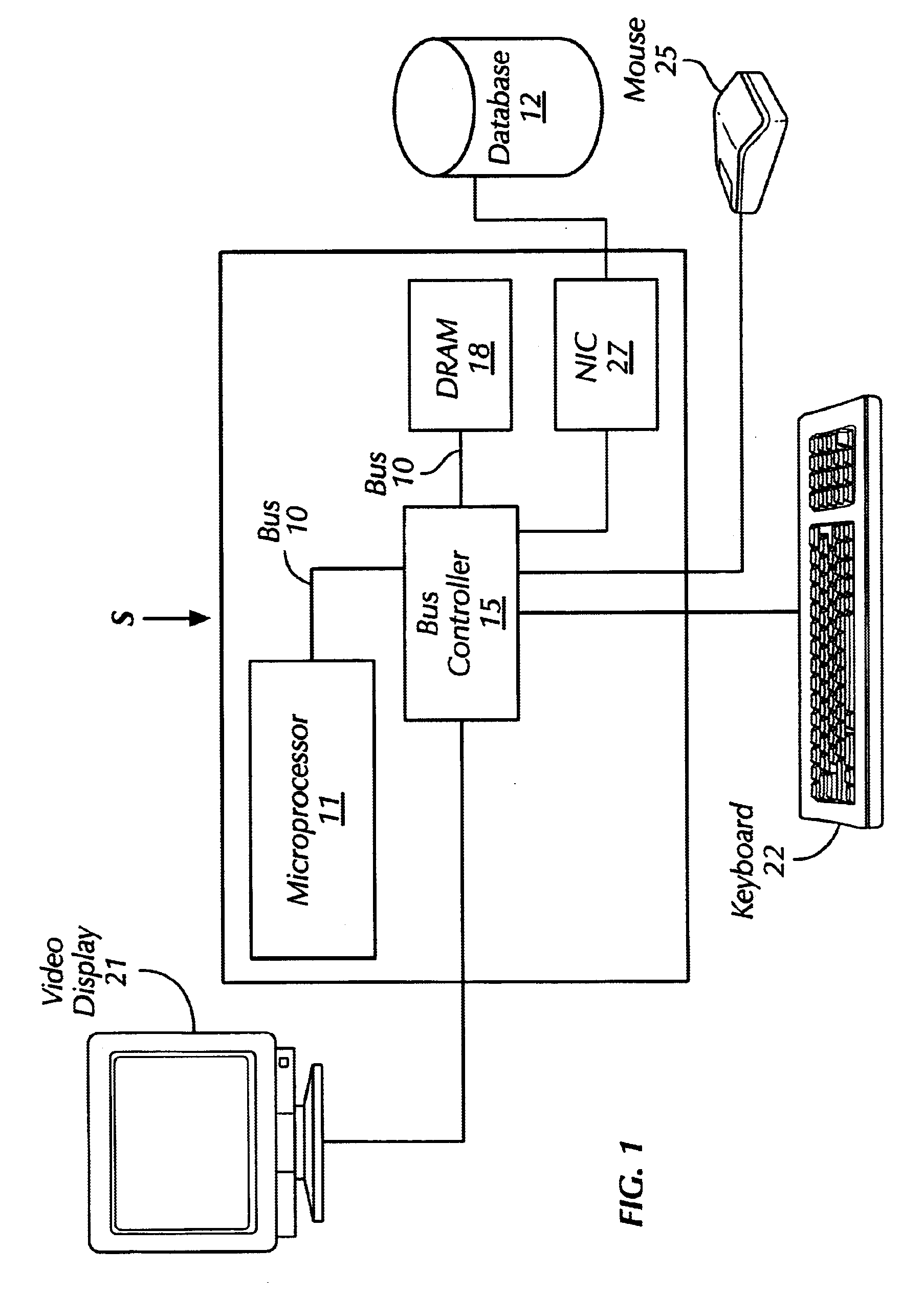
Turning to FIG. 1, illustrated is a computer system S upon which a graphical user interface (GUI) according to the invention can be run. The computer system S is typically a UNIX-based workstation. The computer system S may be configured around an internal bus 10 connected to a microprocessor 11 and a bus controller 15. Also included within the illustrated computer system S and connected to the bus 10 is a dynamic random access memory (DRAM) or other form of system memory 18, and a network interface card (NIC) 27. The NIC 27 is shown coupled through a network to a database 12. Finally, a video display 21, a keyboard 22 and a mouse or other pointing device 25 are connected to the computer system S through circuitry in the bus controller 15, enabling human interaction with the computer system S.

The computer system S is used for illustrative purposes only. The type and nature of the processor 11, the memory 18, and other illustrated hardware components are not critical to the invention...


PUM


Abstract

A template for a logic synthesis command script is broken into smaller and functionally independent templates termed "micro-templates." Using micro-templates, logic synthesis time may be significantly reduced. Each micro-template may correspond to a particular synthesis operation and may be enabled or disabled. Where synthesis of a particular set of synthesis operations is desired, the micro-templates corresponding to those synthesis operations are enabled.

Description

1. Field of the InventionThe present invention relates to a micro-template graphical user interface (GUI) and methodology that enables the user of a script-oriented logic synthesis tool to break a template for a logic synthesis command script into smaller and functionally independent templates termed "micro-templates."2. Description of the Related ArtWith astonishing regularity over the past several decades, transistors have become smaller and the devices that employ them have become more complex. Today it is not uncommon for an integrated circuit (IC) to contain millions of transistors. The job of designing these ICs has also grown correspondingly more difficult. What was once accomplished by a single individual or a small group of individuals is typically performed by a large team or multiple teams of designers.Although microprocessors and microcontrollers have become more difficult to design, a number of tools have been developed to make the job easier. One class of tools that ma...

Claims


Application Information

Patent Timeline
Patent Type & Authority Patents(United States)
IPC IPC(8): G06F9/00G06F9/44
CPCG06F8/38G06F9/45512
Inventor DOUGHERTY, W. DAVID
Owner GLOBALFOUNDRIES INC
Learn More