
System for discovering and maintaining geographic location information in a computer network to enable emergency services

Inactive Publication Date: 2003-12-16
CISCO TECH INC
View PDF4 Cites 222 Cited by
  • Summary
  • Abstract
  • Description
  • Claims
  • Application Information

AI Technical Summary

Benefits of technology

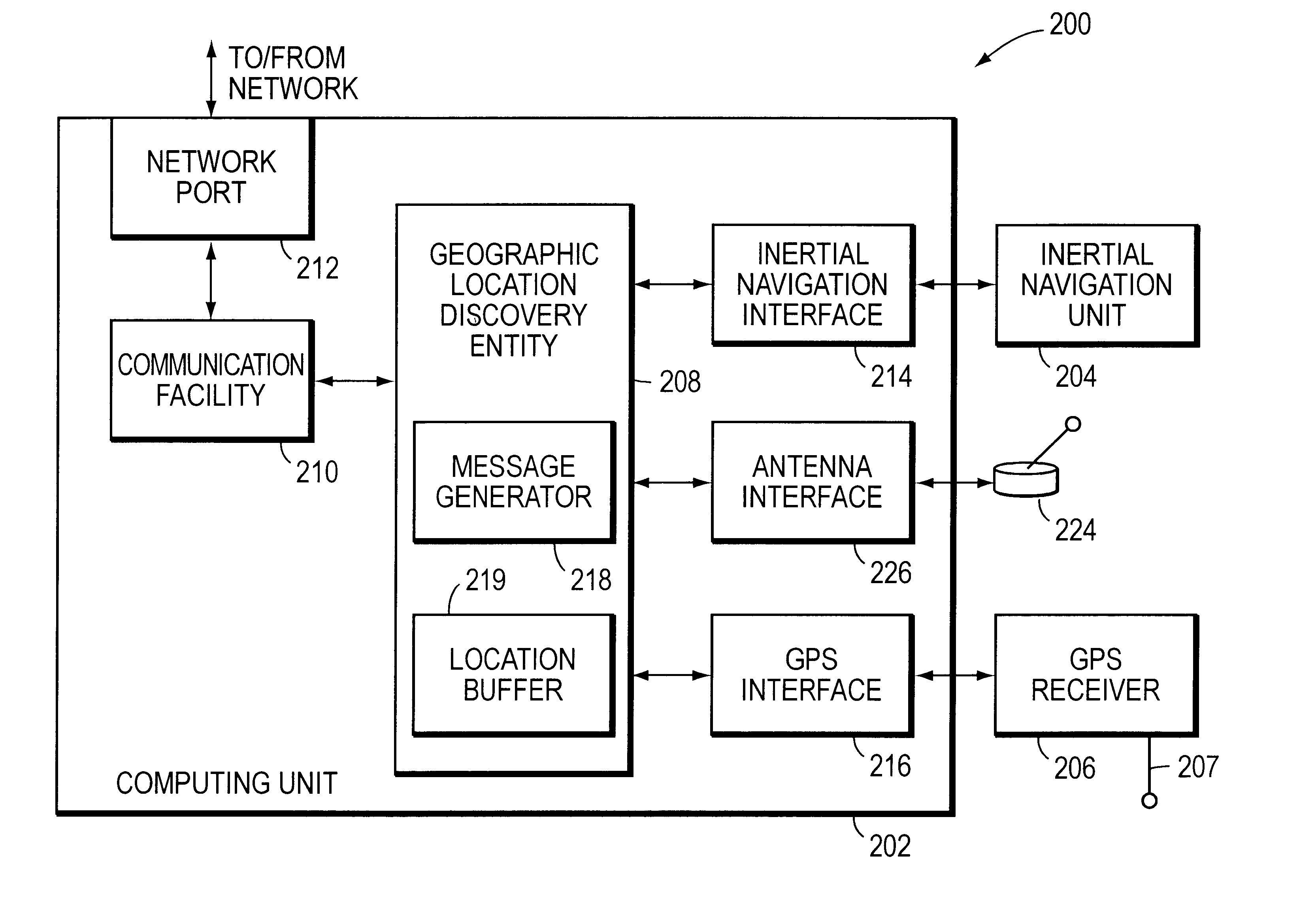
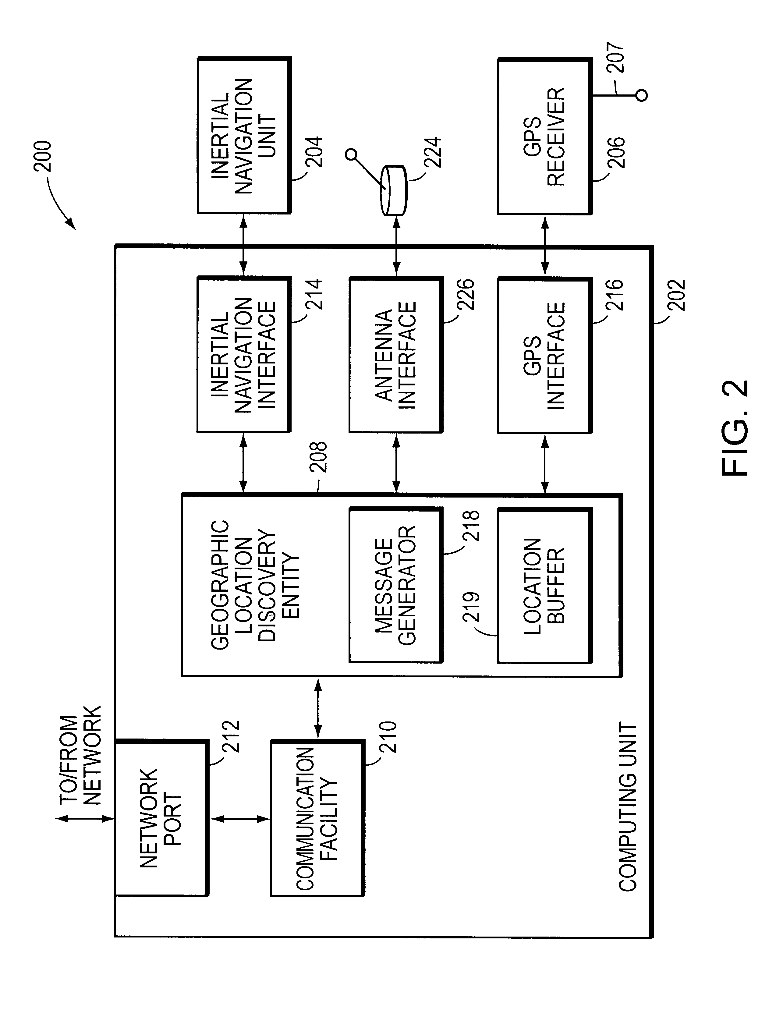
Briefly, the present invention is directed to a system for discovering and maintaining geographic location information for computer networks. In accordance with a preferred embodiment, the system includes a computing unit, such as a laptop, notebook or palm personal computer (PC), and a geographic location generator, such as a Global Positioning System (GPS) receiver. The computing unit includes a location discovery entity and a message generator. The GPS receiver, which is mounted to and in communication with the computing unit, may be augmented with an inertial navigation unit to facilitate the generation of location information inside of buildings where GPS signals can be difficult to receive. The computing unit further includes a network interface card (NIC) so that it can communicate with one or more network devices, such as a network switch. The switch includes a location recording / reporting entity and a location database. The recording / reporting entity is configured to receive and recognize messages from the computing unit, and to store information at the location database.

Problems solved by technology

Because the creations of such manual inventories are so time consuming, they are rarely performed.
They are also error-prone, resulting in the data base having incorrect information.
For organizations using a private branch exchange (PBX) telephone switch, however, subscriber information is often limited to the organization's name and its main address.

Method used


Image

  • System for discovering and maintaining geographic location information in a computer network to enable emergency services
  • System for discovering and maintaining geographic location information in a computer network to enable emergency services
  • System for discovering and maintaining geographic location information in a computer network to enable emergency services

Examples


Embodiment Construction

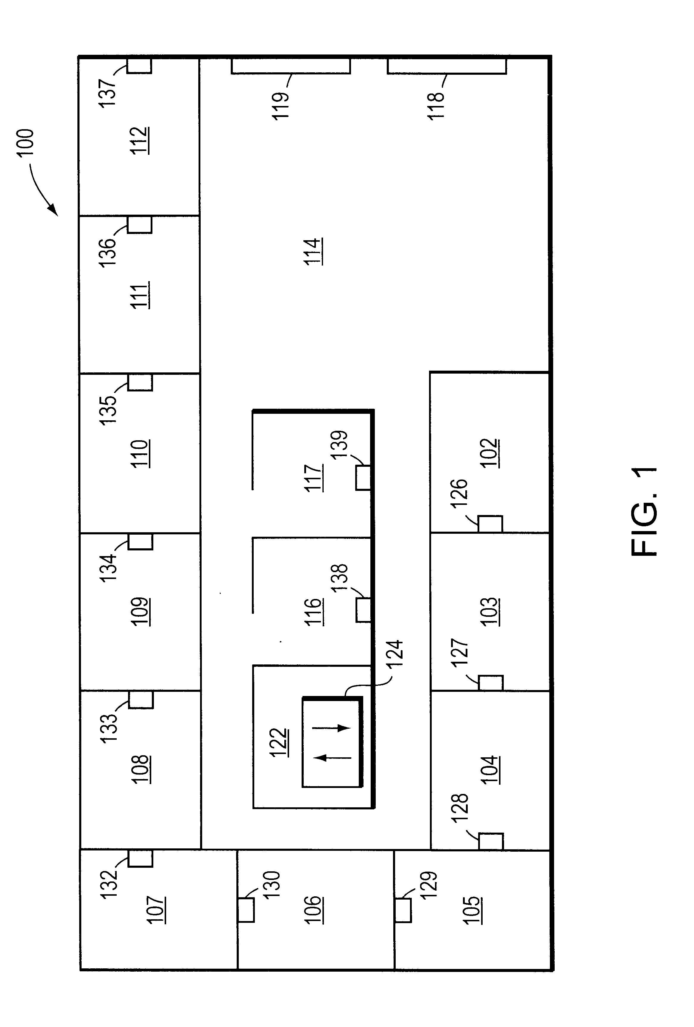
. 1 is a plan view of an exemplary office layout 100. The office layout 100 includes a plurality of offices 102-112, a lobby 114 and two cubicles 116-117. Disposed along an exterior wall of the lobby 114 are two windows 118-119. The office layout 100 further includes a wiring closet 122. Located within the wiring closet 122 are one or more intermediate network devices, such as a network switch 124. Disposed within each office 102-112 and within each cubicle 116-117 is a network connector or outlet 126-139. The network outlets 126-139 are all radially wired to the wiring closet 122 in a conventional manner. Furthermore, as described below, each outlet 126-139 is preferably coupled to a respective port of the network switch 124. Network entities, such as personal computers, printers, scanners, etc. (not shown) may be coupled to the various network outlets 126-139 within the offices 102-112 and cubicles 116-117. Switch 124 provides a switching function among its various ports so as to ...


PUM


Abstract

A system automatically discovers and maintains geographic location information for entities and devices making up a computer network. The system preferably includes a computing unit and a geographic location generator, such as a Global Positioning System (GPS) receiver. The computing unit includes a location discovery entity and a message generator. The GPS receiver, which is mounted to and in communication with the computing unit, may be augmented with an inertial navigation unit to facilitate the generation of location information inside of buildings where GPS signals can be difficult to receive. The computing unit further includes a network communications facility so that it can communicate with one or more network devices, such as a network switch. The switch includes a location recording / reporting entity and a location database. Physical coordinates of network entities or devices are obtained by the GPS receiver and / or-inertial navigation unit and transmitted to the network switch, and the recording / reporting entity stores the physical coordinates at the location database.

Description

1. Field of the InventionThis invention relates to computer networks, and more specifically, to a system for discovering and storing location information for network entities or devices.2. Background InformationComputer networks typically comprise a plurality of interconnected network entities. A network entity may consist of any device, such as a computer or end station, that "sources" (i.e., transmits) or "sinks" (i.e., receives) datagrams (e.g., packets and / or frames). A common type of computer network is a local area network ("LAN") which typically refers to a privately owned network within a single building or campus. LANs typically employ a data communication protocol (LAN standard), such as Ethernet, FDDI or token ring, that defines the functions performed by the data link and physical layers of a communications architecture (i.e., a protocol stack). In many instances, several LANs may be interconnected by point-to-point links, microwave transceivers, satellite hookups, etc. ...

Claims


Application Information

Patent Timeline
IPC IPC(8): G01S5/00G01S5/14H04Q7/38G01S19/42
CPCG01S5/0027G01S19/17G01S2205/006G01S5/0236
Inventor ORAN, DAVID R.GAI, SILVANO
Owner CISCO TECH INC
Learn More