Close-up attachment lens

a technology of attachment lens and lens body, which is applied in the field of close-up attachment lens, can solve the problems of difficulty in attaching lens, inapplicability to other taking lens bodies with different configurations, and large aberrations of various kinds,

Inactive Publication Date: 2003-12-09
FUJI PHOTO OPTICAL CO LTD
View PDF5 Cites 4 Cited by
  • Summary
  • Abstract
  • Description
  • Claims
  • Application Information

AI Technical Summary

Benefits of technology

When the close-up attachment lens according to the invention is mounted on the taking lens body including the first lens group for focusing, the second lens group for changing a magnification, the third lens group for compensating a shift of an image plane and the fourth lens group for forming an image, preferable performance can be delivered. The close-up attachment lens functions as a lens with a configuration having two lens groups with three lenses comprising the cemented lens having a negative refractive power and the third lens having a positive refractive power. The cemented lens includes the first lens with a convex surface on the object side having a positive refractive power and the second lens with a concave surface on the image side having a negative refractive power. The close-up attachment lens is mounted to be capable of shooting a subject in a close range in which the taking lens body cannot cover while maintaining practical optical performance.

Problems solved by technology

However, it is difficult for the attachment lens with such a simple configuration to satisfy optical performance requirements in a whole zoom (magnification change) range of the taking lens body on which the attachment lens is mounted.
Hei 5-224121) is applied to the zoom lens with such a configuration, aberrations of various kinds are too large and not suitable for practical use.
Thus, the attachment lens which has been conventionally proposed is applicable to the taking lens body comprising the fourth unit in charge of compensating a shift of the image plane and adjusting the focus, so it is not suitably applicable to any other taking lens bodies with different configurations.
As a result, the whole lens system can focus on a subject in a close range which does not allow the taking lens body TL to focus thereon, so an image is formed on the imaging surface IMG.

Method used


Image

  • Close-up attachment lens
  • Close-up attachment lens
  • Close-up attachment lens

Examples


example 1

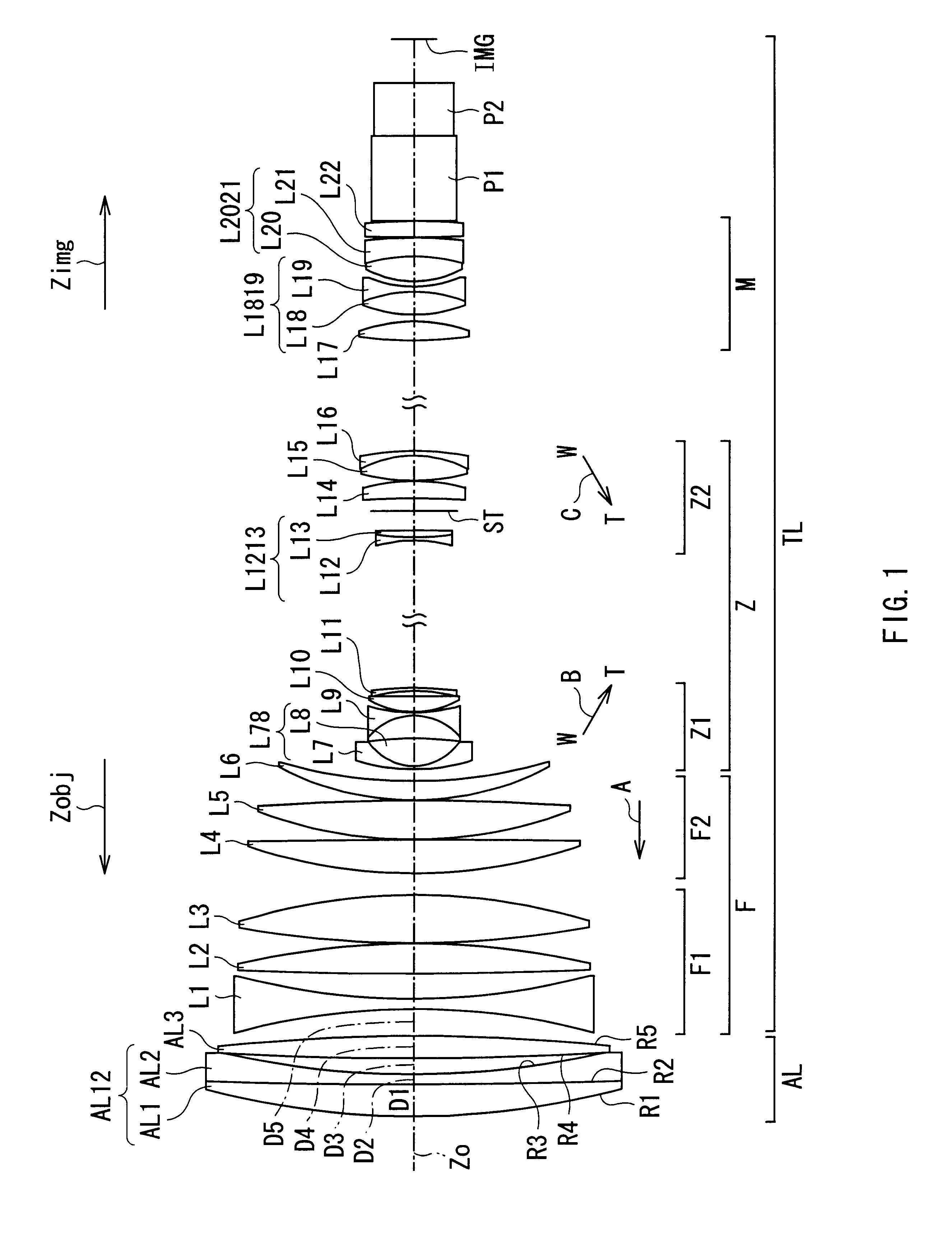
The cross-sectional configuration and the zoom system of an attachment lens and a taking lens body according to an example are the same as those shown in FIG. 1.

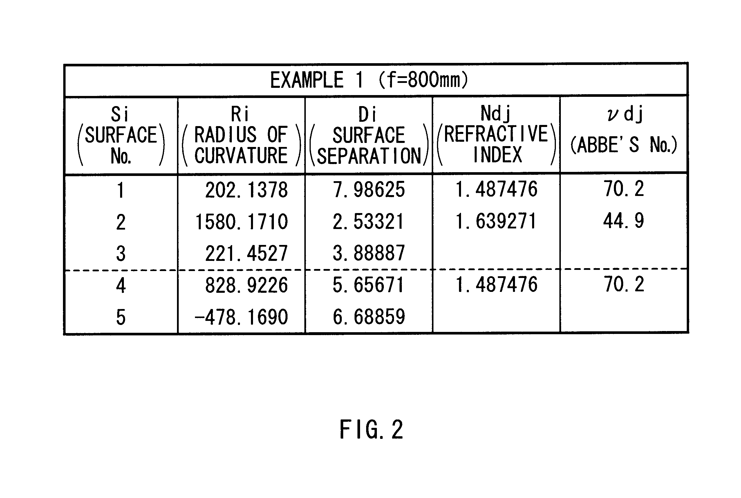
FIG. 2 shows a specific numerical data table regarding the configuration of the attachment lens AL of the example. In the table, the column of surface number Si shows the number of lens surface increasing as the lens surface is closer to the image plane side, assuming a lens surface closest to the object side is the first lens surface. The column of radius of curvature Ri corresponds to the symbol Ri shown in FIG. 1, and the column shows the radius of curvature of the ith lens surface from the object side. The column of surface separation Di also corresponds to the symbol Di shown in FIG. 1, and the column shows the surface separation in a direction of the optical axis between the ith lens surface Si from the object side and the i+1th lens surface Si+1. The radius of curvature Ri and the surface separation Di are expressed i...

example 2

The cross-sectional configuration and zoom system of the attachment lens and the taking lens body according to another example are the same as those shown in FIG. 1.

FIG. 7 shows specific numerical data regarding the configuration of the attachment lens AL of the example. The attachment lens AL of the example has a focal length of 600 mm.

In the example, a focal length f12 of the cemented lens AL12 is "-2400 mm", a focal length f3 of the third lens AL3 is "473 mm", so they satisfy the conditional expression (1). Further, like Example 1, the Abbe numbers vd1 and vd2 of the first lens AL1 and the second lens AL2 forming the cemented lens AL12 are "70.2" and "44.9", respectively, so they are within a range of the conditional expressions (2) and (3).

FIGS. 8A to 8C and FIGS. 9A and 9C show various aberrations at the wide end and at the tele end, respectively, in a state that the attachment lens AL of the example is mounted on the taking lens body TL. In the example, the overall focal lengt...

example 3

The cross-sectional configuration and zoom system of the attachment lens and the taking lens body according to a still another example are the same as those shown in FIG. 1.

FIG. 10 shows specific numerical data regarding the configuration of the attachment lens AL of the example. The attachment lens AL of the example has a focal length of 400 mm.

In the example, a focal length f12 of the cemented lens AL12 is "-1484 mm", a focal length f3 of the third lens AL3 is "311 mm", so they satisfy the conditional expression (1). Further, like Example 1, the Abbe numbers .nu.d1 and .nu.d2 of the first lens AL1 and the second lens AL2 forming the cemented lens AL12 are "70.2" and "44.9", respectively, so they are within a range of the conditional expressions (2) and (3).

FIGS. 11A to 11C and FIGS. 12A to 12C show various aberrations at the wide end and at the tele end, respectively, in a state that the attachment lens AL of the example is mounted on the taking lens body TL. In the example, the o...


PUM


Abstract

Provided is a close-up attachment lens suitably applicable to a taking lens body comprising a lens group in charge of a focus function and a lens group in charge of a zoom function completely separate from each other. The attachment lens is mounted on the taking lens body on an object side for close-up shooting. The attachment lens comprises a cemented lens having a negative refractive power as a whole, the cemented lens including a first lens with a convex surface on an object side having a positive refractive power and a second lens with a convex surface on an image plane having a negative refractive power, and a third single lens having a positive refractive power. The taking lens body comprises a focus lens group, a zoom lens group and a master lens group which are disposed independently of one another. The use of the attachment lens allows close-up shooting while maintaining various aberrations in a taking lens in a favorable condition.

Description

1. Field of the InventionThe present invention relates to a close-up attachment lens used through mounting on a taking lens with a zoom function, and more specifically a close-up attachment lens suitably used for, for example, a professional use (broadcasting) television camera.2. Description of the Related ArtIn general, zoom lenses are used for shooting cameras such as broadcasting cameras, etc. In such a zoom lens, an attachment lens is often mounted on a front or rear side of a main lens system (taking lens body) to be capable of close-up shooting. Conventionally, in most cases, such a close-up attachment lens comprises one or two single lenses. However, it is difficult for the attachment lens with such a simple configuration to satisfy optical performance requirements in a whole zoom (magnification change) range of the taking lens body on which the attachment lens is mounted.For example, in Japanese Unexamined Patent Publication No. Hei 5-224121, a close-up attachment lens comp...

Claims


Application Information

Patent Timeline
Patent Type & Authority Patents(United States)
IPC IPC(8): G02B15/00G02B15/10
CPCG02B15/10
Inventor SHINOHARA, YOSHIKAZU
Owner FUJI PHOTO OPTICAL CO LTD
Why Eureka
Try Eureka