
Random microembossed receptor media

Inactive Publication Date: 2003-11-18
3M INNOVATIVE PROPERTIES CO
View PDF89 Cites 81 Cited by
  • Summary
  • Abstract
  • Description
  • Claims
  • Application Information

AI Technical Summary

Benefits of technology

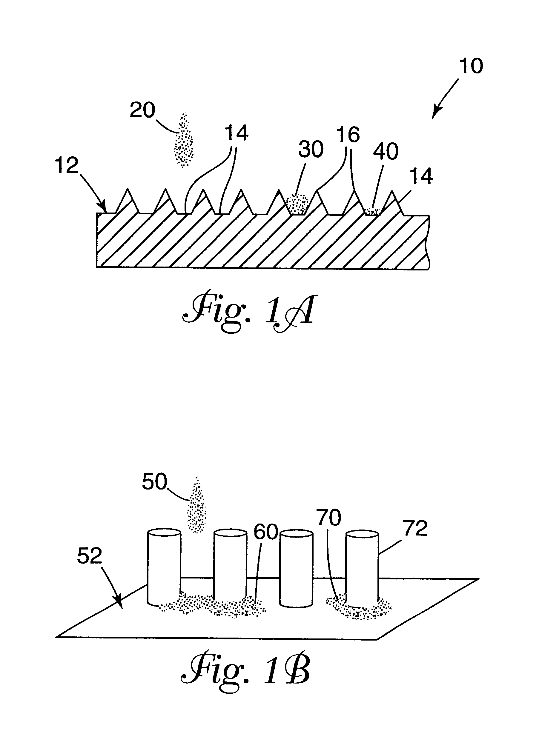
An advantage of the invention is the minimization of common inkjet printing problems, such as banding, feathering, bleeding, and mudcracking, by altering the receiving surface of the inkjet receptor medium rather than altering the formulation of the inkjet inks.
is the minimization of common inkjet printing problems, such as banding, feathering, bleeding, and mudcracking, by altering the receiving surface of the inkjet receptor medium rather than altering the formulation of the inkjet inks.
Another advantage of the invention is the ease by which a microembossed image surface can be formed.
Another advantage of the present invention is the protection of the inkjet image from abrasion at the surface of the inkjet receptor medium because the colored entities forming the image reside within or around elements of the topography of the microembossed image surface. As such, the medium of the present invention provides abrasion resistance, smear resistance, and prevention of feathering or bleeding of the image.
Another advantage of the invention is the usefulness of the microembossed image surface with organic solvent-based, water-based, phase change, or radiation polymerizable inks. The inks can further comprise either dye or pigment based colorants.
The use of random surface patterns of the present invention can also give some advantages over engineered, reproducible, patterns, including lack of Moire' effect, higher tolerance of cosmetic defects, and potentially lower costs of tool generation.

Problems solved by technology

Another could be the time and expense involved with using the high precision machines needed to produce the master patterns.

Method used


Image

  • Random microembossed receptor media

Examples


example 1

Generation of Microembossed Films

A polyethylene (PE) layer on paper, "MQ-1" obtained from Felix Schoeller Technical Papers of Germany, was prepared with a random pattern according to the methods outlined in U.S. Pat. No. 4,025,159, incorporated herein by reference. The surface of the PE was thus covered with roughly hemispherical voids 50-85 micrometers in diameter, most lying in the 70-80 micrometer range. The SEM as FIG. 2 illustrates the appearance of the PE film after bead removal. This substrate will be referred to as SUBSTRATE 1 and is seen in FIG. 2.

Some of this material was subsequently flattened by compression molding against a smooth RTV silicone surface. This material will be referred to as CONTROL 1. Samples of SUBSTRATE 1 and CONTROL 1 were printed upon with several printers. SUBSTRATE 1 was also used further to make the same random hemispherical void pattern in other thermoplastics. A piece of SUBSTRATE 1 was used as a template to cast a curable silicone ("SLASTIC J" t...

example 2

Print Tests of SUBSTRATE 1 and CONTROL 1

Printer: HP855Cse. Excellent image quality and resolution was observed when TEST PATTERN 1 was printed in plain paper mode at normal speed on SUBSTRATE 1. Qualitative comparison of CONTROL 1 to SUBSTRATE 1, showing the strong effect of print resolution using only the surface pattern (without further coatings, etc.) is exemplified in FIGS. 3 and 4, respectively.

Printer: HP2500CP. This printer, used to print the TEST PATTERN 3 test pattern, caused some ink bleed on SUBSTRATE 1 in areas of high color fill. Also, the dry time in the areas showing ink bleed was poor. Other than this, the quality of the print was very good, with good color density. SOLUTION 1 and SOLUTION 2 were coated onto two samples of SUBSTRATE 1 using a #3 Mayer rod; after drying, the coated substrates were subjected to the same print tests. No ink bleed was observed, and dry times were less than 5 minutes even in the high color fill areas. Also, image density was improved in b...

example 3

Print Tests on SUBSTRATE 2 and CONTROL 2

HP2000. SUBSTRATE 2 and CONTROL 2 were used to print TEST PATTERN 1 in plain paper mode / normal quality. FIGS. 13 and 14, respectively, show the difference in the prints obtained. In general, the observations for SUBSTRATE 2 vs. CONTROL 2 were the same as those made for SUBSTRATE 1 vs. CONTROL 1.


PUM

PropertyMeasurementUnit
Thicknessaaaaaaaaaa
Volumeaaaaaaaaaa
Volumeaaaaaaaaaa

Abstract

A receptor medium with a sheet having a random microembossed imaging surface as one major surface thereof. The receptor medium can receive jettable materials, which include inks, adhesives, biological fluids, chemical assay reagents, particulate dispersions, waxes, electrically, thermally, or magnetically modifiable materials, and combinations thereof. The random microembossed medium unexpectedly solves such common inkjet printing problems as feathering, banding, and mudcracking in inkjet printing systems by controlling how an inkjet drop contacts and dries on an inkjet receptor medium and also Moire' effects. Clear lines of demarcation between adjoining colors of a pigmented inkjet image graphic can be obtained without creation of the Moire' effects. Methods of making and using the inkjet receptor medium are also disclosed.

Description

This application relates to inkjet printing media to improve drying times of the inkjet ink, improve abrasion resistance of the inkjet image after drying, and prevent visual defects caused by ink beading, ink spreading, or mudcracking, resulting in improved print quality.BACKGROUND OF INVENTIONImage graphics are omnipresent in modern life. Images and data that warn, educate, entertain, advertise, etc. are applied on a variety of interior and exterior, vertical and horizontal surfaces. Nonlimiting examples of image graphics range from advertisements on walls or sides of trucks, to posters that advertise the arrival of a new movie, warning signs near the edges of stairways, and the like.The use of thermal and piezo inkjet inks has greatly increased in recent years with accelerated development of inexpensive and efficient inkjet printers, ink delivery systems, and the like.Thermal inkjet hardware is commercially available from a number of multinational companies, including without limi...

Claims


Application Information

Patent Timeline
IPC IPC(8): B41M5/00B41M5/52B41M5/50B41M3/00B41J2/01
CPCB41M5/0047B41M5/0064B41M5/52B41M3/006B41M5/504B41M5/508Y10T428/24942Y10T428/24901Y10T428/24802Y10T428/2495Y10T428/24884Y10T428/31855Y10T428/249996B33Y80/00
Inventor ENGLE, LORI P.FEHR, ROBERT T.FLEMING, PATRICK R.GRAHAM, PAUL D.HUNTLEY, DOUGLAS A.LEMIRE, VERNA J.SOLOMON, JEFFREY L.WILLIAMS, TODD R.YLITALO, CAROLINE M.
Owner 3M INNOVATIVE PROPERTIES CO
Learn More