Piezoelectric element having thickness shear vibration and mobile communication device using the same
a technology of shear vibration and piezoelectric elements, applied in the direction of piezoelectric/electrostrictive device details, device material selection, device details, etc., can solve the problems of large spurious response, difficult miniaturization, and difficult formation of a wide band filter with quartz
- Summary
- Abstract
- Description
- Claims
- Application Information
AI Technical Summary
Problems solved by technology
Method used
Image
Examples
embodiment 1
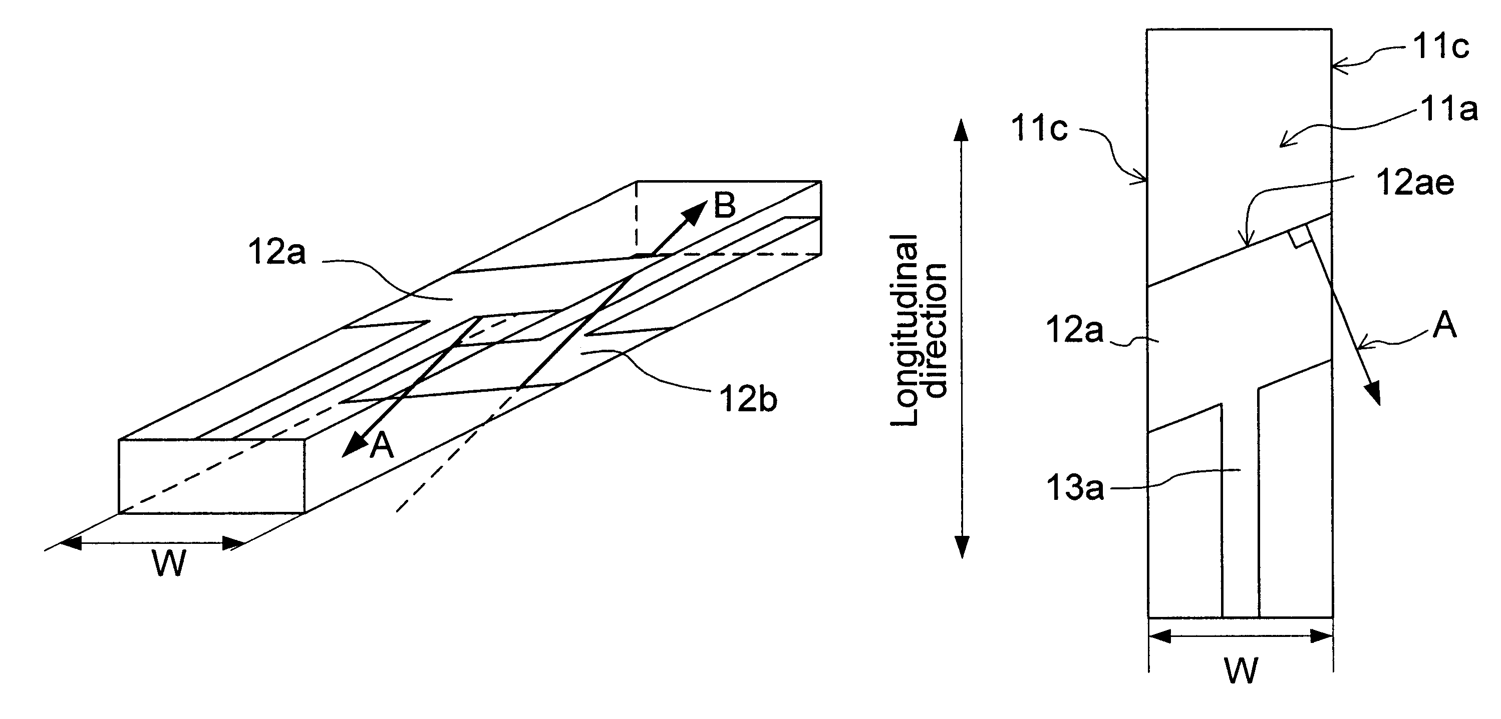
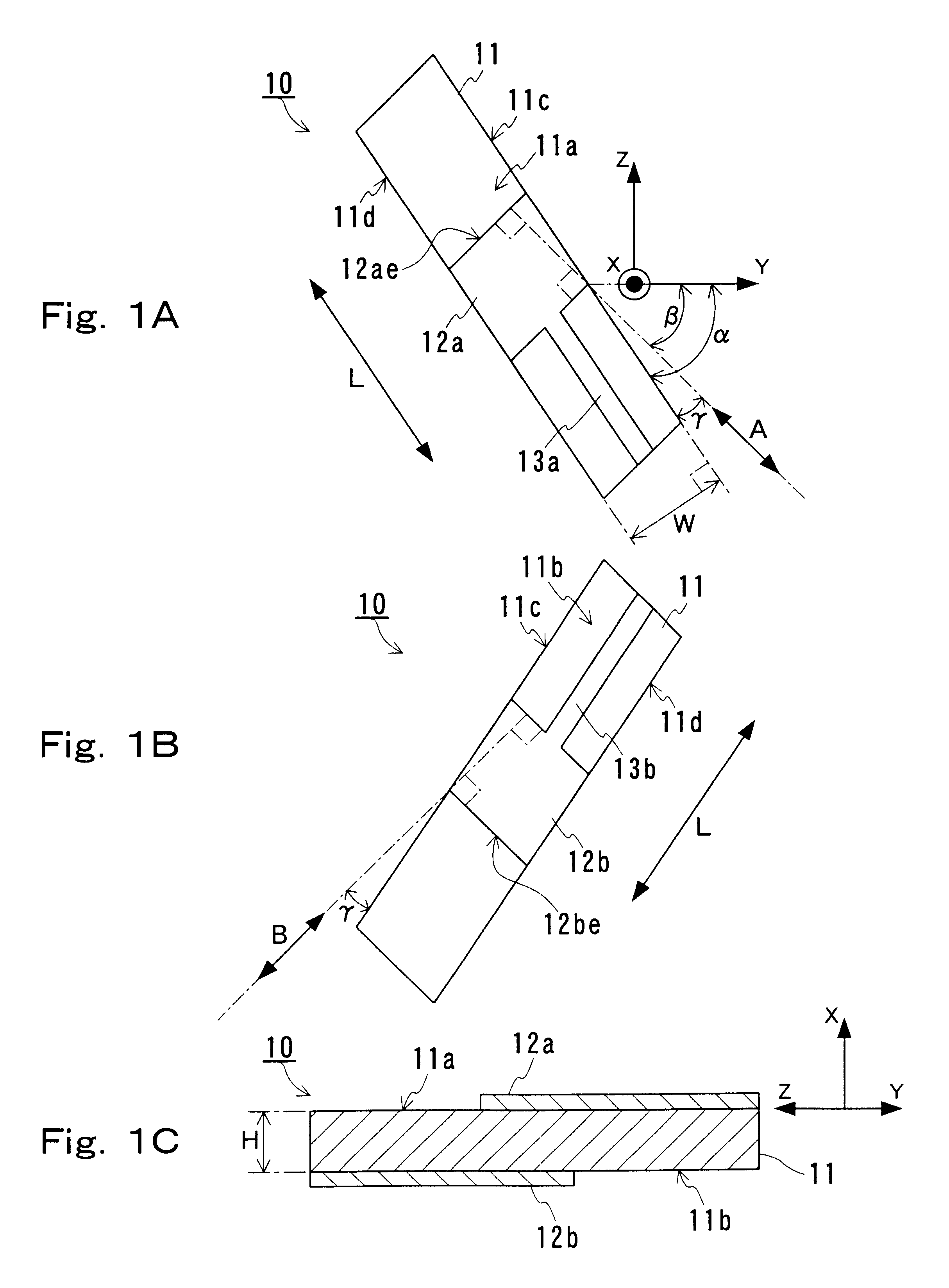
In Embodiment 1, an example of a piezoelectric vibrator will be described as a piezoelectric element of the present invention. FIG. 1A is a plan view of a piezoelectric vibrator 10 of Embodiment 1 from a first principal plane side. FIG. 1B is a plan view from a second principal plane side. FIG. 1C is a cross-sectional view of the central portion in the longitudinal direction of the element. FIGS. 1A and 1C also show the directions of the crystalline axes of a piezoelectric substrate 11.
Referring to FIGS. 1A to 1C and FIGS. 9A and 9B, the piezoelectric vibrator 10 includes a piezoelectric substrate 11 and a pair of exciting electrodes 12a and 12b formed on the piezoelectric substrate 11. The exciting electrodes 12a and 12b are connected to electrodes 13a and 13b for interconnection, respectively. The electrodes for interconnection can be formed along the entire width in the traverse direction of the piezoelectric substrate 11, as shown in FIGS. 3A to 3F.
The materials for the exciting...
embodiment 2
In Embodiment 2, another example of a piezoelectric vibrator will be described. A piezoelectric vibrator 10a of Embodiment 2 is the same as the piezoelectric vibrator 10 described in Embodiment 1 except for the substrate, so that duplicate description will be omitted.
FIG. 4A is a plan view of a piezoelectric vibrator 10a of Embodiment 2 from a first principal plane side. FIG. 4B is a plan view from a second principal plane side. FIG. 4C is a cross-sectional view of the central portion of the piezoelectric vibrator. FIG. 4A also shows the directions of the crystalline axes of a first piezoelectric substrate 31a and a second piezoelectric substrate 31b.
Referring to FIGS. 4A to 4C, the piezoelectric vibrator 10a includes a piezoelectric substrate 31, an exciting electrode 12a formed on the first principal plane of the piezoelectric substrate 31 and an exciting electrode 12b formed on the second principal plane opposed to the first principal plane. The exciting electrodes 12a and 12b ar...
embodiment 3
In Embodiment 3, a piezoelectric filter of the present invention will be described by way of an example of a dual mode piezoelectric filter. The same components as those of the piezoelectric vibrator 10 of Embodiment 1 bear the same reference numerals, and will not be described further.
FIG. 5A is a plan view of a piezoelectric filter 40 of Embodiment 3 from a first principal plane side. FIG. 5B is a plan view from a second principal plane side. FIGS. 5A also shows the directions of the crystalline axes of a piezoelectric substrate 11.
Referring to FIGS. 5A to 5C, the piezoelectric filter 40 of Embodiment 3 includes a piezoelectric substrate 11, an input electrode 41 and an output electrode 42 formed on a first principal plane 11a of the piezoelectric substrate 11, and a ground electrode 43 formed on a second principal plane 11b oppose to the first principal plane. The ground electrode 43 is formed on the second principal plane 11b in a position corresponding to the input electrode 41...
PUM
 Abstract
Description
Claims
Application Information
 - Generate Ideas
- Intellectual Property
- Life Sciences
- Materials
- Tech Scout
- Unparalleled Data Quality
- Higher Quality Content
- 60% Fewer Hallucinations
Browse by: Latest US Patents, China's latest patents, Technical Efficacy Thesaurus, Application Domain, Technology Topic, Popular Technical Reports.
© 2025 PatSnap. All rights reserved.Legal|Privacy policy|Modern Slavery Act Transparency Statement|Sitemap|About US| Contact US: help@patsnap.com


