
Aircraft noise reduction apparatus

Inactive Publication Date: 2003-09-16
AIRBUS OPERATIONS LTD
View PDF13 Cites 39 Cited by
  • Summary
  • Abstract
  • Description
  • Claims
  • Application Information

AI Technical Summary

Benefits of technology

Preferably a said attachment is shaped to avoid or minimise an air stagnation region forming in front thereof when positioned on the landing gear and in use. Such stagnation regions tend to increase both drag and noise emanating downstream of the stagnation region. The term "in front of" as used herein refers to a position upstream in the airflow, during flight.
An advantage of the undertray not extending above and behind the bogie beam is that inspection and maintenance access and air cooling are not thereby prevented by the attachment.
Where the bogie beam is tilted upwardly at the front, during approach, the area of the bogie beam left exposed is downstream of the undertray and thus the passage of high speed air past noise inducing components associated with the bogie beam is prevented by the undertray attachment.
The undertray may have a single curvature aerodynamic surface and may be of a width to permit air to pass between the undertray and wheels on the bogie to cool brakes. Preferably the undertray includes a forward upwardly extending aerodynamic surface blended smoothly into an under surface extending underneath and along the bogie beam, desirably with a further surface extending longitudinally of the bogie beam on either side of the undertray depending from lateral edges of the undertray, preferably orthogonal to the said aerodynamic surface. In this way air spilling over each lateral edge of the undertray in the region of wheel brakes will be able freely to flow past the brakes but will not be accelerated past the brakes by any funneling effect of the surface contours of the undertray.
Where the landing gear includes a door attached thereto extending in a generally streamwise direction to one side of a main leg of the landing gear a said attachment may comprise a deflector fairing extending from the door in front of at least the main leg of the landing gear. Preferably the fairing is positionable in sealing engagement with the door and may additionally extend in front of any further struts, stays and / or actuators for the landing gear located in the vicinity of the main leg thereby to deflect air away from all said landing gear components. For a main landing gear having a drag stay extending upwardly in the vicinity of the main leg and a retraction actuator similarly extending upwardly in the vicinity of the main leg, the said fairing not only achieves deflection of the air away from any noise inducing fittings on the main leg, but also deflects air away from passages formed between any combination of the main leg, the actuator, the drag stay and the main leg door where air would otherwise be accelerated therethrough usually past sundry noise inducing fittings.
The front portion of the undertray desirably has extension portions to extend around the lower articulation link fairing and thus provide a smooth airflow in this area, upon approach to landing. Generally a main landing gear with a bogie will approach landing with the rear wheels deflected downwardly and the front wheels deflected upwardly. The undertray and lower articulation link fairing thus desirably lie closely adjacent one another when the bogie is in approach configuration.

Problems solved by technology

Noise emanating from commercial aircraft, whether cargo aircraft and / or passenger carrying aircraft, is now an important environmental issue.
This in turn has led to greater noise being generated by each aircraft in its approaches to the airport.
Modem high bypass ratio turbofan engines are now extremely quiet on approach to landing and dominant noise on some aircraft types, perceived at ground level, is starting to become the noise generated by landing gear and by high lift devices on the wings.
Although noise is likely to be induced by any element which creates turbulence in the airflow past the landing gear, those elements which have been found particularly likely to create high noise levels are as follows: elements which act as Helmholz resonators such as hollow axles, apertures, fastener fittings, spindles, etc; also elements likely to create small vortices such as small protuberances, sharp edges; dresssings such as small pipes, tubes, cables, and coil springs, etc.
Although wind tunnel tests have been carried out on landing gear fully enclosed by fairings to determine noise levels in the far field, such full enclosure fairings are normally completely impractical for everyday use on an aircraft.
This is because articulation of the landing gear during deployment and retraction movement is prevented by the fairings and because very limited stowage space in the landing gear bay in most aircraft will not accommodate full enclosures owing to the space which they take up.
Additionally, full enclosure fairings render daily visual inspection regimes and maintenance of the landing gear almost impossible.
Firstly, this is because visible inspection through such fairings is generally impossible and secondly because regular removal of such fairings for inspection or maintenance is far too time consuming and difficult.
To date therefore no practical solution to the problem of landing gear induced airframe noise has been found.
Such stagnation regions tend to increase both drag and noise emanating downstream of the stagnation region.
Such a steering mechanism has been found to be prone to noise inducement including, as it usually does, many sharp edges, apertures and sundry pipe and cable work.
Similarly, the axle attachment deflects air away from another region of the landing gear particularly prone to noise inducement, i.e. the joint between the main leg and the axle, again liable to include sundry sharp edged fittings and pipe and cable work.

Method used


Image

  • Aircraft noise reduction apparatus
  • Aircraft noise reduction apparatus
  • Aircraft noise reduction apparatus

Examples


Embodiment Construction

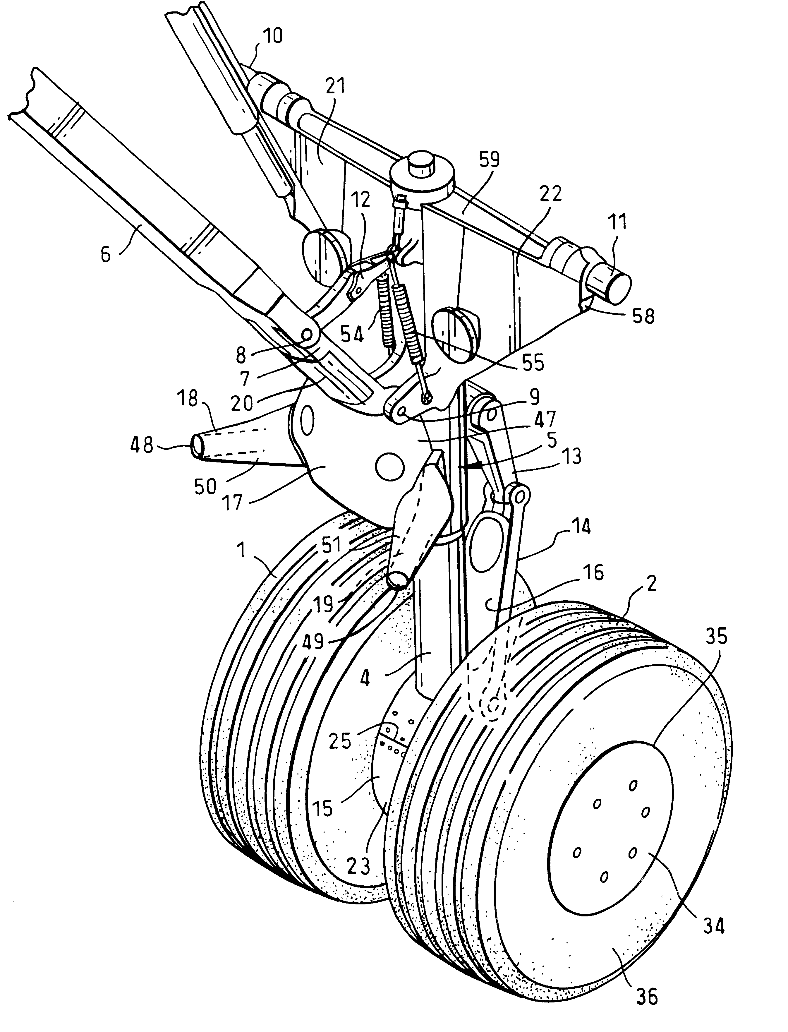
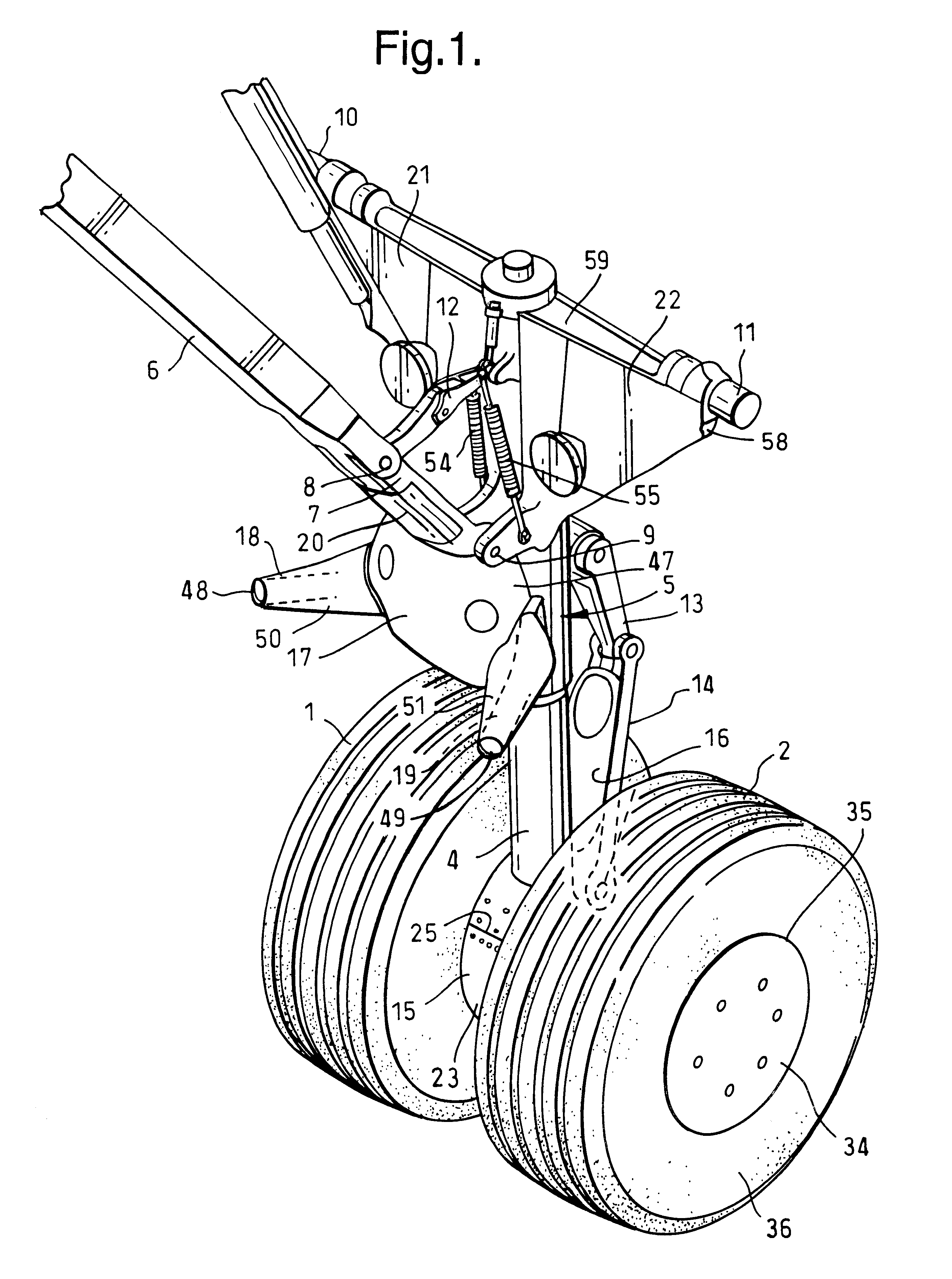
Referring to FIGS. 1 and 3, an aircraft nose landing gear is shown having wheels 1, 2, an axle 3 (see FIG. 3), a main telescopic leg 4, and steering mechanism shown generally at 5, an upper drag stay 6 pivotally connected to a lower drag stay 7 at pivot 8 and to the leg 4 at pivot 9, pintle bearings 10, 11, a drag stay release mechanism 12 and torque links 13, 14. The nose gear is fitted with various noise-reducing attachments as follows. All have been designed to provide the most streamlined shape commensurate with maximum total noise reduction and providing room for articulation of the landing gear during use, during retraction / deployment and during stowage. Drag may actually be increased owing to the fitting of the attachments. Shown in FIGS. 1 and 3 is an axle fairing attachment 15; a lower torque link attachment 16 (shown in FIG. 1 only); a steering mechanism attachment 17; steering actuator covers 18, 19; a lower drag stay attachment 20 and main fitting attachments 21, 22.

Refe...


PUM


Abstract

An aircraft, aircraft landing gear and apparatus including at least one attachment (15,17,76,93,94,111) for noise reduction purposes are provided. Such attachments are shaped and positioned on the landing gear to deflect air away from noise-inducing components (64,65) of the landing gear and to permit deflection and articulation movement and also stowage of the landing gear whilst the attachments are installed thereon. The attachments are not designed to be drag-reducing.

Description

1. Field of the InventionThe invention relates to aircraft noise reduction apparatus, in particular to apparatus to reduce noise emanating from landing gear of the aircraft when deployed on approach to landing.2. Discussion of Prior ArtThe invention has particular application to commercial aircraft when landing at airports in or near to built up areas where aircraft approach noise is an increasing nuisance with increasing frequency of use of airports and ever larger aircraft. Noise emanating from commercial aircraft, whether cargo aircraft and / or passenger carrying aircraft, is now an important environmental issue. The increasing frequency of use of airports has led to aircraft of increasing size being used. This in turn has led to greater noise being generated by each aircraft in its approaches to the airport. Modem high bypass ratio turbofan engines are now extremely quiet on approach to landing and dominant noise on some aircraft types, perceived at ground level, is starting to b...

Claims


Application Information

Patent Timeline
IPC IPC(8): B64C25/00B64C25/16B64C7/00
CPCB64C7/00B64C25/16B64C2025/003B64C25/001
Inventor CHOW, LEUNG CFOOT, DAVID AWOOD, CHRISTOPHER N
Owner AIRBUS OPERATIONS LTD
Learn More