Disk drive apparatus

a technology of disk drive and floppy disk, which is applied in the direction of electric apparatus casings/cabinets/drawers, instruments, casings/cabinets/drawers, etc., can solve the problems of increasing the number of components in the disk drive apparatus, the size and weight of the disk drive are disadvantageously increased, and the floppy disk can be damaged upon head landing and/or takeoff, so as to reduce the number of parts and reduce the size. , the effect o

Inactive Publication Date: 2003-05-27
SONY CORP
View PDF8 Cites 3 Cited by
  • Summary
  • Abstract
  • Description
  • Claims
  • Application Information

AI Technical Summary

Benefits of technology

It is a further object of the present invention to provide a disk drive apparatus which is miniaturized in size, reduced in weight and reduced in its number of parts.
It is yet another object of the present invention to provide a disk drive apparatus for a high density disk-shaped recording medium which reduces the chance of damage to the disk upon head landing and / or takeoff.
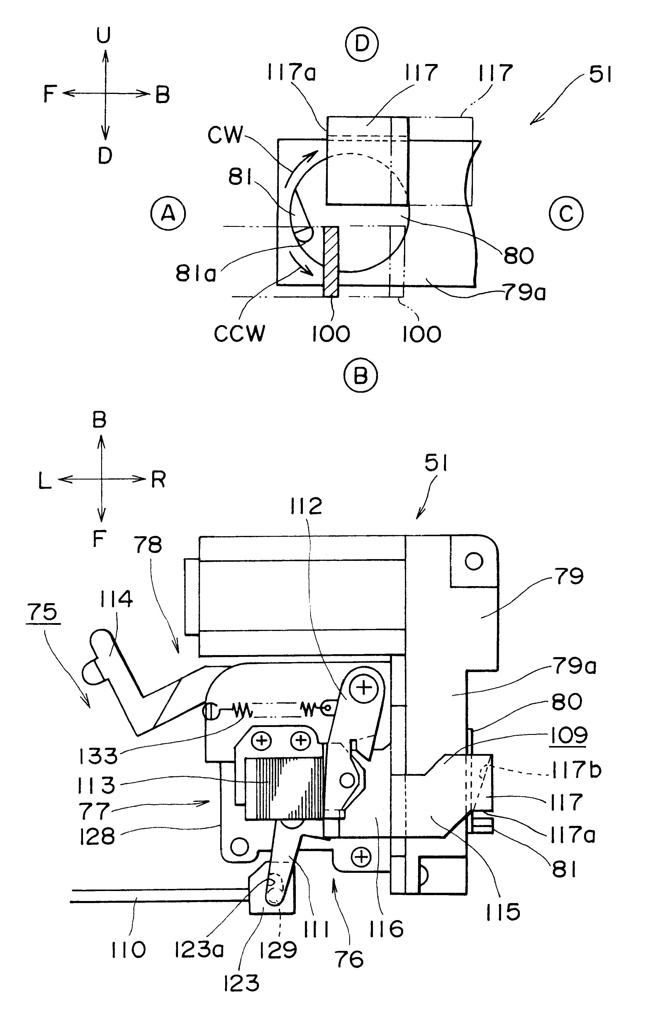
Accordingly, with the disk drive apparatus of the present invention, unloading (ejection) of the disk cartridge and loading (landing) and / or unloading (takeoff) of the head onto / from a disk-shaped recording medium can be performed by a single driving source. Accordingly, by miniaturization and reduction in weight of the drive apparatus as well as reduction of the number of parts of the drive apparatus can be achieved. Further, since the outputting section of the driving member is moved at a low speed and head loading is performed by the head lifting mechanism, so-called "soft landing" of the head onto the disk can be realized. Consequently, damage to the disk upon head landing can be reduced.
Accordingly, with the disk drive apparatus of the present invention, while the biasing force by the biasing member in the unloading direction of the head from the disk is attenuated, so-called "soft takeoff" of the head from the disk can be realized. Consequently, damage to the disk upon takeoff can be reduced.

Problems solved by technology

However, in such a conventional disk drive apparatus as described above, since the ejection operation and the head lifting mechanism are operated by driving sources different from each other, the size and the weight of the disk drive disadvantageously increases as well as the number of components increases in the disk drive apparatus.
However, a floppy disk of a high density developed by the inventor of the present invention (the floppy disk is hereinafter described) has a problem also in that, since the magnetic layer is a thin film, if a conventional disk drive apparatus is used, the floppy disk can be damaged upon head landing and / or takeoff.

Method used


Image

  • Disk drive apparatus
  • Disk drive apparatus
  • Disk drive apparatus

Examples


Embodiment Construction

Referring now to the drawings, wherein like reference minerals are used to designate like features in the several view, certain preferred embodiments of a disk drive apparatus in accordance with the teachings of the present invention are illustrated.

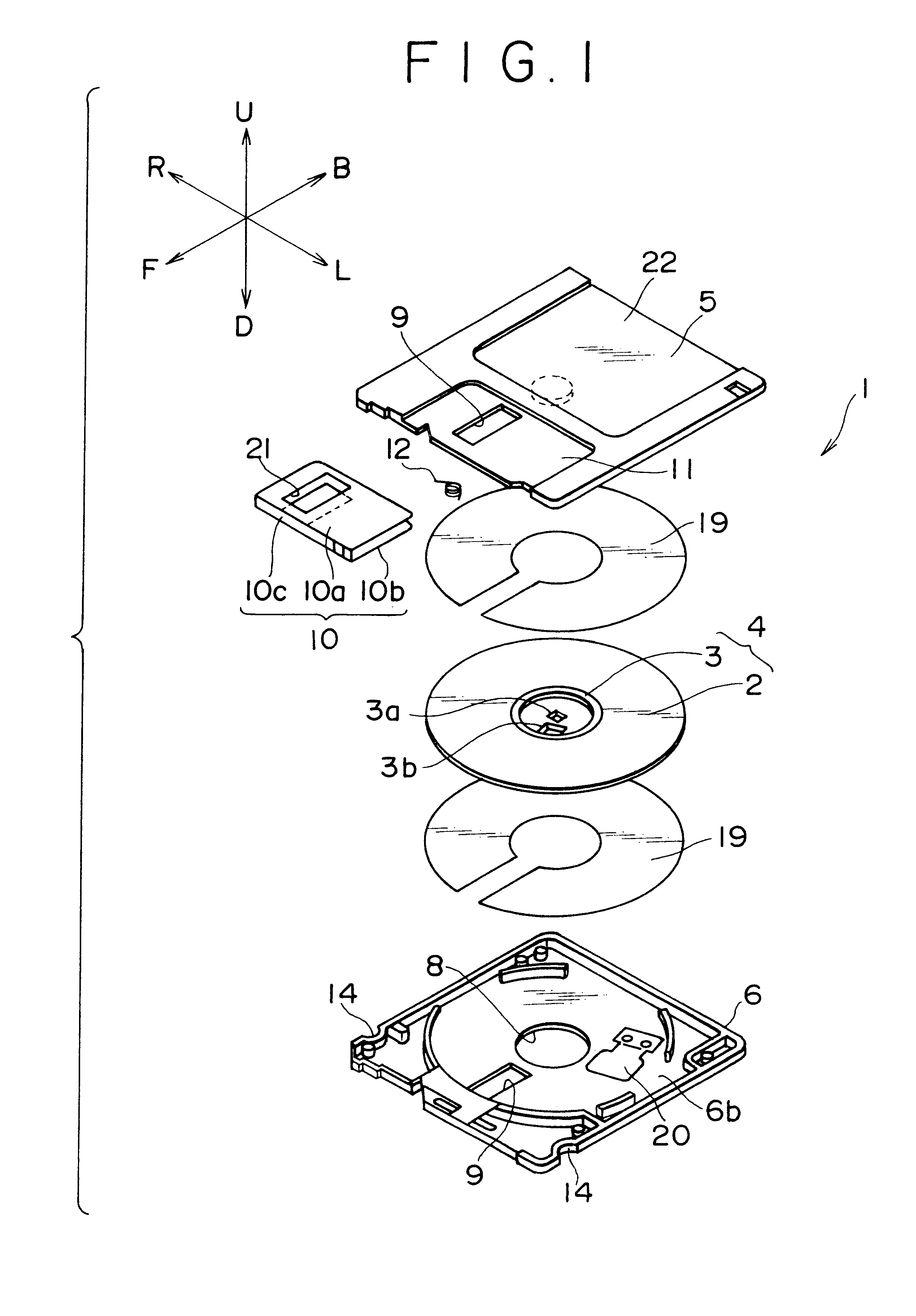
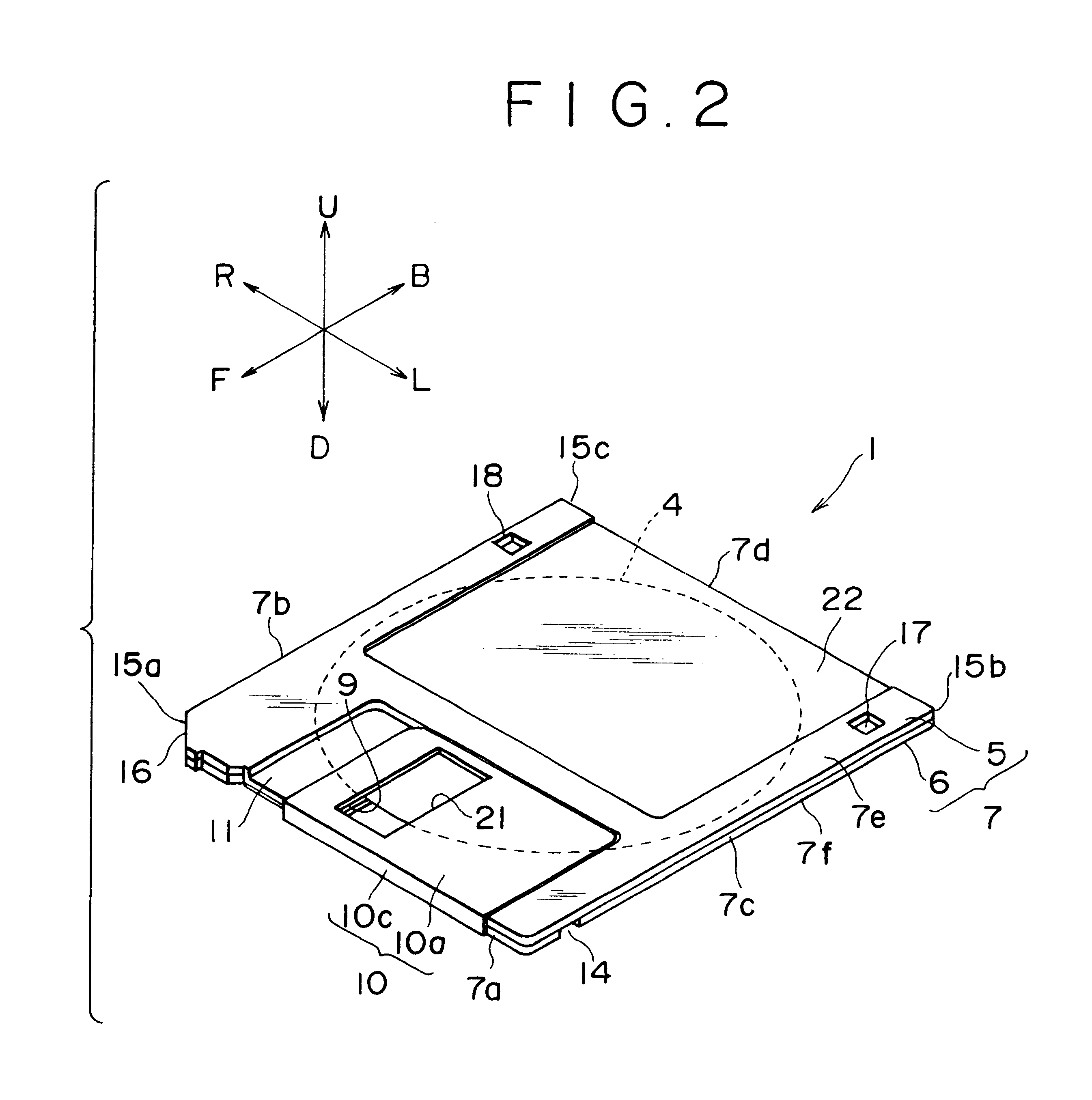
As shown therein, the disk drive apparatus of the present invention is related to a floppy disk drive apparatus (hereinafter referred to as "FD drive apparatus") which can perform recording / reproduction onto / from both a small capacity floppy disk (hereinafter referred to simply as "FD") and a large capacity floppy disk (hereinafter referred to simply as "HiFD") and which is externally provided for a so-called computer mainframe.

In the following, the FD drive apparatus and a FD cartridge and a HiFD cartridge which are used by the FD drive apparatus are described in the following order.

(1) Outline of the FD and the HiFD

(2) FD cartridge

(3) HiFD cartridge

(4) Outline of the FD drive

(5) Frame body

(6) Insulator

(7) Chassis

(8) Disk rotational dri...


PUM


Abstract

To perform ejection of a disk cartridge and head loading (landing) and / or unloading (takeoff) with a single driving source and prevent damage to a disk upon head landing and takeoff. A cam protrusion which is an outputting section of a geared motor is moved at a low speed and acts upon a head lifting mechanism by which, by rotation of the geared motor in one direction (CW direction), ejection of a cartridge is performed, but by rotation in the other direction (CCW direction), landing of magnetic heads is performed for head loading of the magnetic heads.

Description

A. Field of the InventionThe present invention relates to the field of a disk drive apparatus. More particularly, the present invention relates to a disk drive apparatus wherein unloading (ejection) of a disk cartridge and loading (landing) and / or unloading (takeoff) onto and / or from a disk-shaped recording medium can be performed by a single driving source and movement of the head onto and from (head landing, takeoff) the disk-shaped recording medium are performed at a low speed.B. Related ArtConventionally, the operation of ejecting a disk cartridge in which a disk-shaped recording medium, for example, a floppy disk, is accommodated from a cartridge loading condition to a cartridge unloading condition and the operations of loading and unloading a head onto and / or from the disk-shaped recording medium are performed independent of each other. Therefore, respective drive mechanisms (i.e., ejection mechanism, head lifting mechanism) which are independent of each other are provided and...

Claims


Application Information

Patent Timeline
IPC IPC(8): G11B33/08G11B23/03G11B5/54G11B17/04G11B21/12G11B17/043G11B21/02
CPCG11B5/54G11B17/043G11B33/08G11B23/0307G11B21/12
Inventor OTA, TOSHIRO
Owner SONY CORP
Why Eureka
Try Eureka