
Multiple parallel conductor for electrical machines and devices

Inactive Publication Date: 2003-05-13
ASTA ELEKTRODRAHT GMBH
View PDF13 Cites 50 Cited by
  • Summary
  • Abstract
  • Description
  • Claims
  • Application Information

AI Technical Summary

Benefits of technology

Due to the combination of a protective insulation with a mesh-shaped sheathing, both increased mechanical strength and higher dielectric strength are achieved, so that the individual multiple parallel conductors of a winding can be arranged directly above one another or next to one another without interposition of spacers, and without impairing the electrical characteristics. Due to the free accessibility of the surfaces, which are not in contact with one another, of the multiple parallel conductor to the cooling medium and the good cooling characteristics of a multiple parallel conductor provided with a mesh-shaped sheathing, adequate cooling of the conductor or, respectively, of the winding is ensured. The space factor and, consequently, the production costs for a winding can thus be further reduced, and the operational reliability further increased, by this solution according to the invention.
In a preferred embodiment of the multiple parallel conductor according to the invention, the protective insulation comprises one or more side faces and the edge areas, facing this side face or these side faces, respectively, of the adjacent side faces not provided with protective insulation and, if necessary, the edge areas between adjacent side faces provided with protective insulation. This provides for increased protection of the conductor in the area of the edges so that the dielectric strength can be further increased.
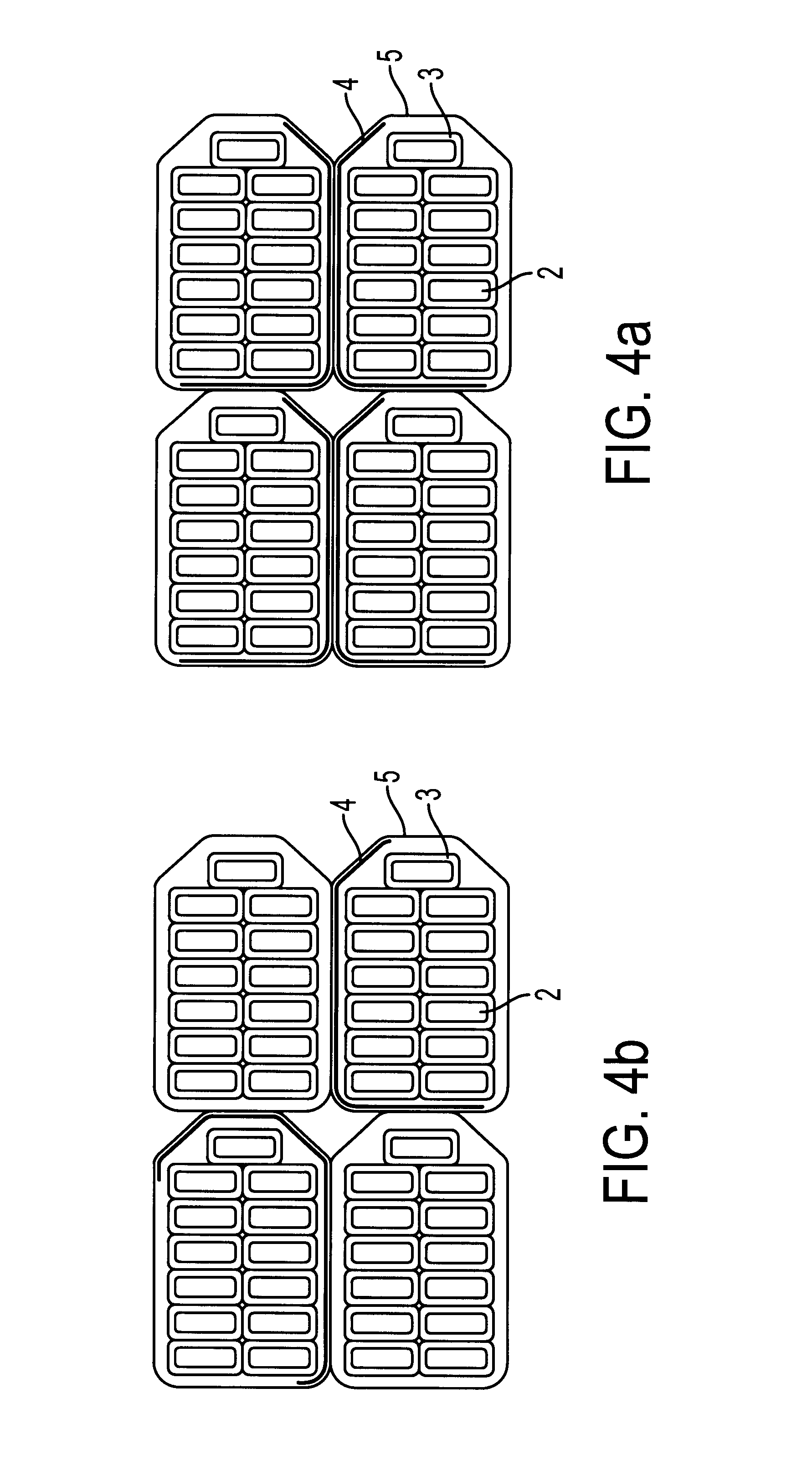
In a winding in which adjacent multiple parallel conductors are in contact with one another over two side faces, e.g. in a group of four, the protective insulation preferably covers at least two adjacent side faces of the multiple parallel conductor in order to provide for all-round protection of the multiple parallel conductor.

Problems solved by technology

If a multiple parallel conductor of this type is processed in such a manner that individual windings or parallel-wound multiple parallel conductors lie directly against one another, there is a risk that the enamel insulation of the subconductors becomes damaged due to friction and that this impairs the electrical characteristics of the winding.
Having regard to a compact and solid conductor, this type of design is disadvantageous since it requires double and triple insulating layers at least in sections.
Furthermore, this conductor is characterized by comparatively poor cooling characteristics.

Method used


Image

  • Multiple parallel conductor for electrical machines and devices
  • Multiple parallel conductor for electrical machines and devices
  • Multiple parallel conductor for electrical machines and devices

Examples


Embodiment Construction

The particulars shown herein are by way of example and for purposes of illustrative discussion of the embodiments of the present invention only and are presented in the cause of providing what is believed to be the most useful and readily understood description of the principles and conceptual aspects of the present invention. In this regard, no attempt is made to show structural details of the present invention in more detail than is necessary for the fundamental understanding of the present invention, the description taken with the drawings making apparent to those skilled in the art how the several forms of the present invention may be embodied in practice.

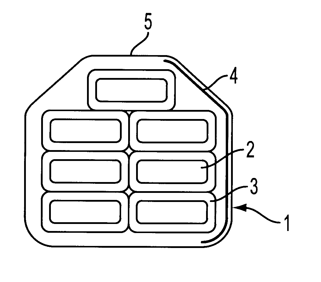
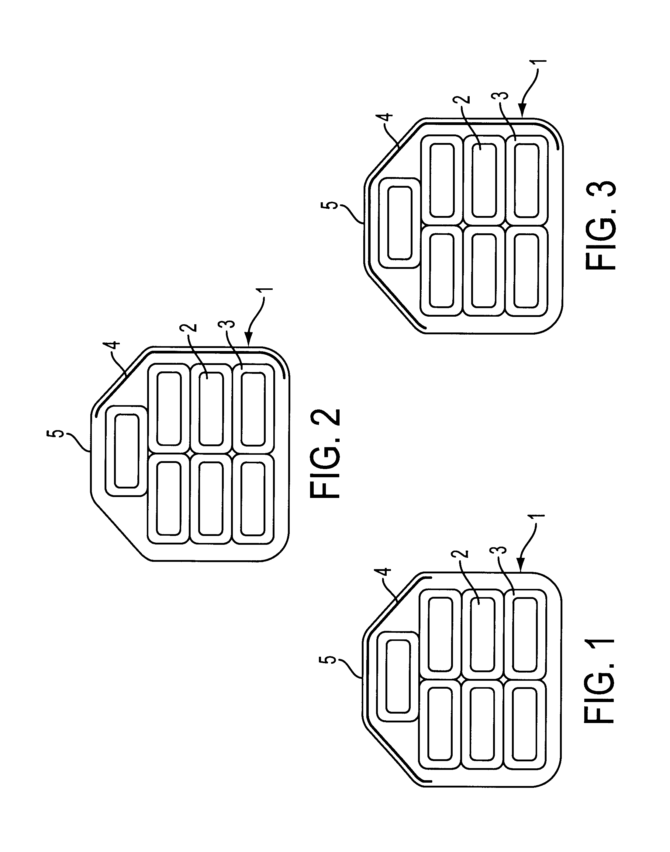
In the text which follows, reference is made to FIG. 1 in which a multiple parallel conductor 1 for an electrical machine is shown using the example of a transposed conductor for the lower-voltage winding of a transformer. The multiple parallel conductor exhibits a number of subconductors 2, e.g. flat copper conductors having a...


PUM


Abstract

Multiple parallel conductor for an electrical machine and process. The conductor includes a plurality of adjacent subconductors combined to form a subconductor bundle having an outer surface with a plurality of contiguous surface sections arranged in a longitudinal direction, and a flat protective insulation covering at least one of the plurality of surface sections. At least one of the plurality of surface sections remains uncovered by the flat protective insulation covering. A mesh sheathing further covers the plurality of surface sections.

Description

1. Field of the InventionThe present invention relates to a multiple parallel conductor for an electrical machine, especially for a transformer, comprising of a plurality of adjacent, preferably mutually insulated subconductors which are combined to form a bundle, and a method for producing such a multiple parallel conductor. Furthermore, the present invention relates to a winding for an electrical machine, especially a transformer comprising a higher-voltage and a lower-voltage winding, comprising of at least one multiple parallel conductor of the abovementioned type, wherein successive windings of the multiple parallel conductor or parallel-wound multiple parallel conductors are arranged axially and / or radially adjacently.2. Discussion of Background InformationTo improve the cooling of electrical conductors, multiple parallel conductors comprising a mesh-shaped wrapping are known. For example, a multiple parallel conductor consisting of a plurality of subconductors or transposed c...

Claims


Application Information

Patent Timeline
IPC IPC(8): H01F27/32
CPCH01F27/323
Inventor PONWEISER, JOHANNSCHNAUBELT, GERNOT
Owner ASTA ELEKTRODRAHT GMBH
Learn More