
Micro-endoscopic system

Inactive Publication Date: 2003-05-13
MICRO INVASIVE TECH
View PDF9 Cites 38 Cited by
  • Summary
  • Abstract
  • Description
  • Claims
  • Application Information

AI Technical Summary

Benefits of technology

The MED comprises a sensor head that contains a sensitive charge coupled device (CCD) sensor array, a light pulse transfer interface and image focus optics. Controls allow the user to control the focus and magnification functions. A removable, one-piece optical probe and ergonomic grip slides over the sensor head to mate with the light pulse transfer interface. The optical probe includes a light pipe to deliver light from the pulse transfer interface to the viewing area and an image path for collecting and guiding reflected light back to the image focus optics. The pulse transfer interface enhances the transfer of light from the fiber optic bundle to the light pipe. Light travels the length of the light pipe and is directed upon the area to be viewed. Light reflected from the viewing area is collected by an object lens and focused into the image path. The image path guides reflected light to the image focus optics in the sensor head where the image is focused on the CCD array. Image data from the CCD array is communicated to the service module electronics through the service cable.
To enhance the intensity of light incident on the optical components of the light path, the MED utilizes a pulsed xenon light source which emits short duration, very high-energy pulses of light. Each pulse of light may be in the energy range of 100,000 watts and have a duration of approximately 10 microseconds. The pulsed xenon light source is essentially a point source of light. The pulsed xenon light source is positioned so the emitted pulses of light pass directly into the input end of the fiber optic bundle. The highly concentrated light energy provides sufficient illumination of the viewing area while employing a smaller diameter light path.
An object of the present invention is to provide a new and improved fine diameter endoscope having an efficient and cost effective construction and which is adaptable for use in out-patient clinics and doctors' offices.
Another object of the present invention is to provide a new and improved fine diameter endoscope which employs novel image collection optics to enhance image quality.
A further object of the present invention is to provide a new and improved fine diameter endoscope which uses a novel pulsed xenon light source to increase the illumination of the viewing area.
A yet further object of the present invention is to provide a new and improved fine diameter endoscope which may be used as an inexpensive real-time diagnostic tool.

Problems solved by technology

Currently available endoscopes have the disadvantages of being bulky, expensive instruments which are typically found only in hospitals.
There are at least two major technical obstacles to the design of an endoscope having an outside diameter of less than 2 mm.
The first obstacle is that of insufficient illumination.
The narrow optical pathways available in a very small diameter endoscope have typically not been capable of transmitting or collecting sufficient light.
In conventional endoscopic systems, these transmission constraints restrict the ability to effectively reduce the diameter of the probe which delivers light into the cavity to be viewed and collects the reflected image.
Light sources of conventional brightness are not compatible with optical transmission systems which employ a significant reduction in the surface area of the light transmission pathway.
Collection of the reflected light which will form an image of the viewing area presents another set of technical difficulties.
However, as the diameter of such a glass rod is reduced, the rod becomes vulnerable to stress induced birefringence, which distorts the image being transmitted.

Method used


Image

  • Micro-endoscopic system
  • Micro-endoscopic system
  • Micro-endoscopic system

Examples


Embodiment Construction

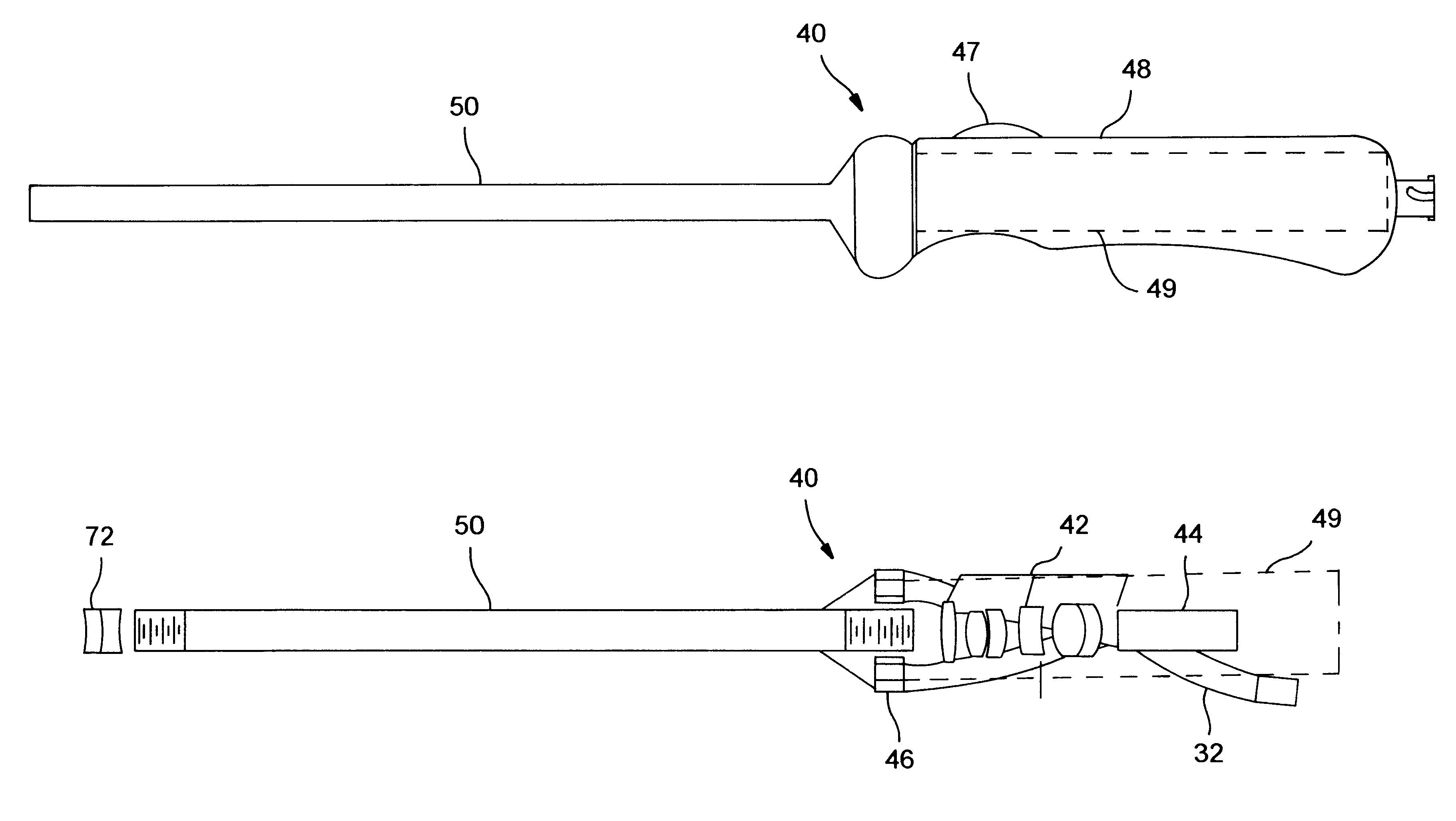
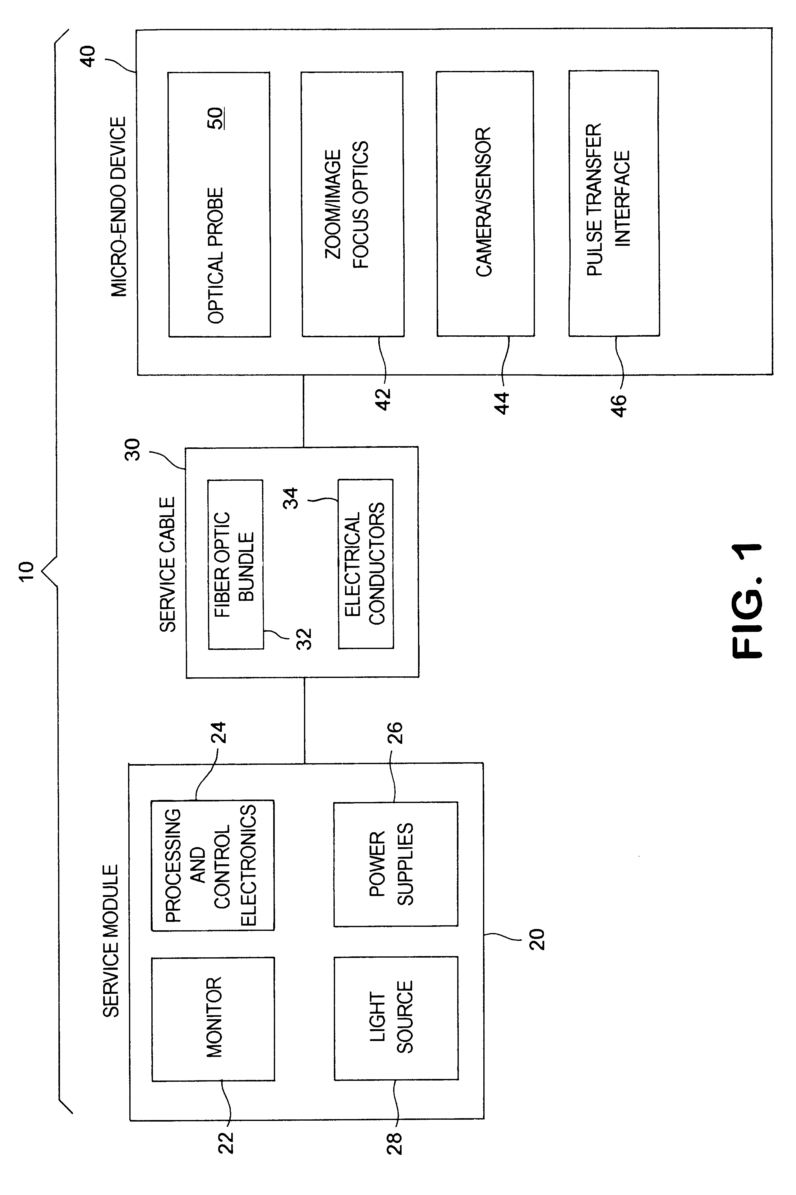
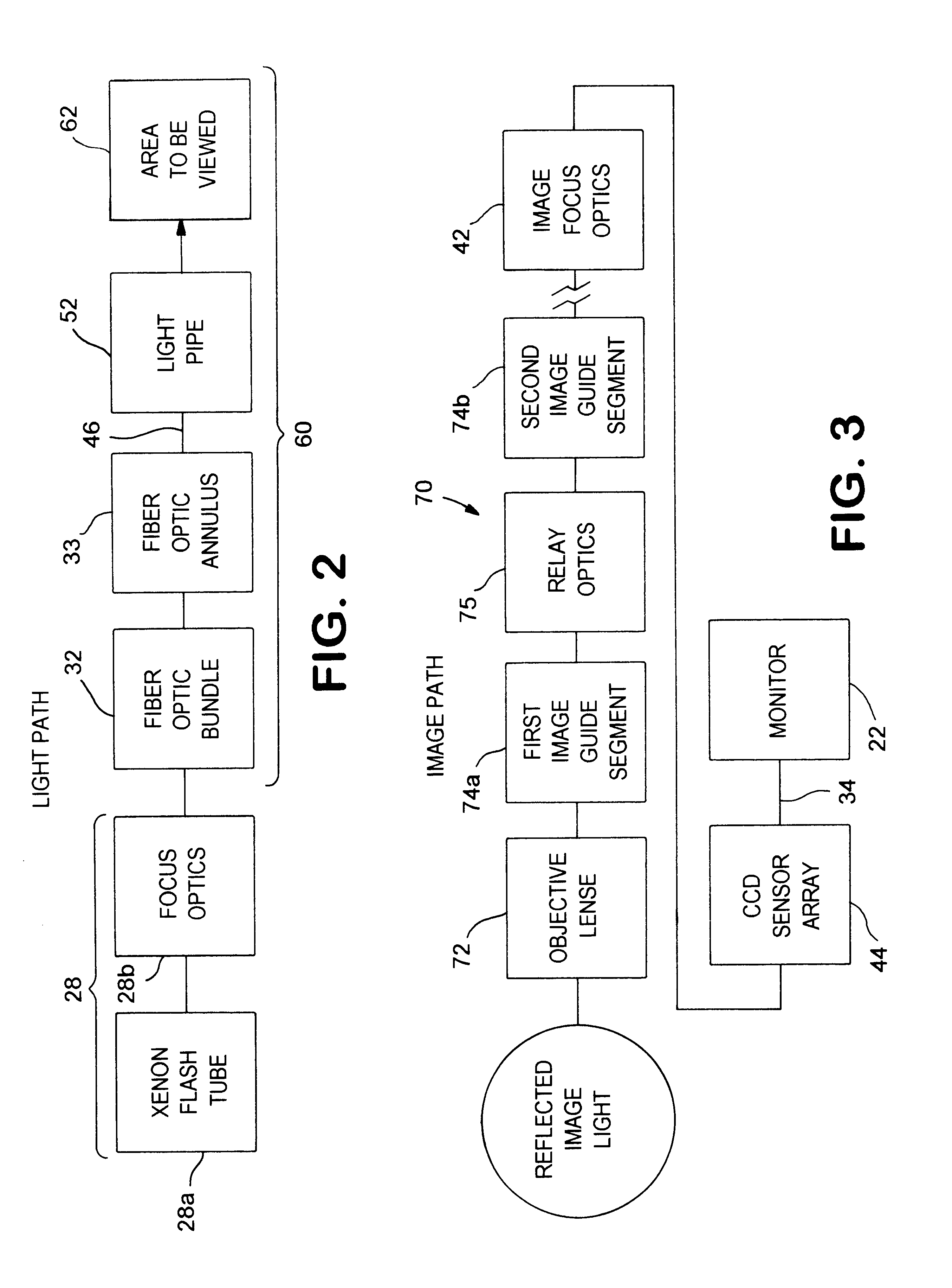
A micro-endoscopic system (ME system) incorporating a micro-endoscopic device (MED) 40 in accordance with the present invention is generally designated by the numeral 10. With reference to FIG. 1, one embodiment of the ME system is comprised of a service module 20, service cable 30 and a MED 40. The service module 20 contains a video monitor 22, a pulsed xenon light source 28, system power supplies 26 and system processing and control electronics 24.

A service cable 30 connects the service module 20 with the MED 40. The service cable includes a fiber optic bundle 32 to transmit light from the light source 28 to the MED 40. The service cable 30 also incorporates electrical conductors 34 to allow the service module 20 to communicate with the electronic portions of the MED 40. Because of the compact size of the ME system 10, the service cable may be as short as 2 meters. A short service cable 20 increases the amount of light reaching the viewing area by limiting the distance dependent l...


PUM


Abstract

A micro-endoscopic system employs a pulsed xenon light source and image collection optics with a fine diameter optical probe for an endoscope. Very bright pulses of light emitted by a xenon flash tube increase the intensity of light incident on the light transmitting optics, allowing a reduction in size of the optical components, resulting in a corresponding reduction in the size of the optical probe. A segmented glass image guide directs the reflected light to a sensor array. Segmentation of the image guide avoids the stress related problems associated with fine diameter glass optical structures.

Description

BACKGROUND OF THE INVENTION1. Field of the InventionThis invention relates to endoscopes which are widely used in the field of medicine and in particular to a compact endoscope having a fine diameter probe for use in hospitals and doctors' offices for outpatient procedures.2. Description of the Related ArtCurrently, orthopaedic surgeons perform the greatest number of arthroscopic in-hospital procedures, approximately half of which could be performed on an outpatient basis. Almost 2.5 million such procedures are undertaken annually. Of these, 510,000 are for shoulder injuries, 1.7 million are for knee injuries, and 200,000 are for such procedures as elbows, ankles and wrists. The future arthroscopic market is expected to be additionally enhanced by anticipated developments in the fields of synthetic bone and tissue transplantation.Currently available endoscopes have the disadvantages of being bulky, expensive instruments which are typically found only in hospitals. Available endoscop...

Claims


Application Information

Patent Timeline
IPC IPC(8): A61B1/002A61B1/04A61B1/07A61B1/06
CPCA61B1/042A61B1/055A61B1/00165A61B1/07A61B1/0607
Inventor BALA, JOHN L.
Owner MICRO INVASIVE TECH
Learn More