
Method and apparatus for exchanging data between transactional and non-transactional input/output systems in a multi-processing, shared memory environment

a technology of multi-processing and shared memory, applied in data conversion, multi-programming arrangement, program control, etc., can solve problems such as the inability to dequeue data elements

Inactive Publication Date: 2003-04-29
RPX CLEARINGHOUSE
View PDF15 Cites 44 Cited by
  • Summary
  • Abstract
  • Description
  • Claims
  • Application Information

AI Technical Summary

Benefits of technology

In summary, the present invention provides a machine readable storage medium containing a program element to implement a queuing system, also referred to as a Flexible Input / output Queuing System (FIQS). Such a queuing system may be used to exchange data elements such as IO commands or application data between application software and an IO service layer. The queuing system includes a queue data structure, preferably a circular queue data structure and two pointers that control the enqueuing of data elements to the queue and the dequeuing of data elements from the queue. One of the pointers is a write pointer and the other pointer is a read pointer. The circular queue data structure allows for running process elements to be inserted into and removed from the queue without blocking each other.
This novel queuing system is particularly useful for multiprocessor computing platforms. By forcing the IO service layer and the IO software applications to communicate via the queuing system data structure, non-blocking access between the IO software applications is permitted in a multiprocessor system. The queuing system can support multiple IO service calls from different software applications in a robust manner and may avoid becoming blocked by a single software application.

Problems solved by technology

A data element may not be dequeuable for a number of reasons, such as the application software may have written but not yet committed the data to the queue, the application software may have stopped running, or any other reason.

Method used


Image

  • Method and apparatus for exchanging data between transactional and non-transactional input/output systems in a multi-processing, shared memory environment
  • Method and apparatus for exchanging data between transactional and non-transactional input/output systems in a multi-processing, shared memory environment
  • Method and apparatus for exchanging data between transactional and non-transactional input/output systems in a multi-processing, shared memory environment

Examples


Embodiment Construction

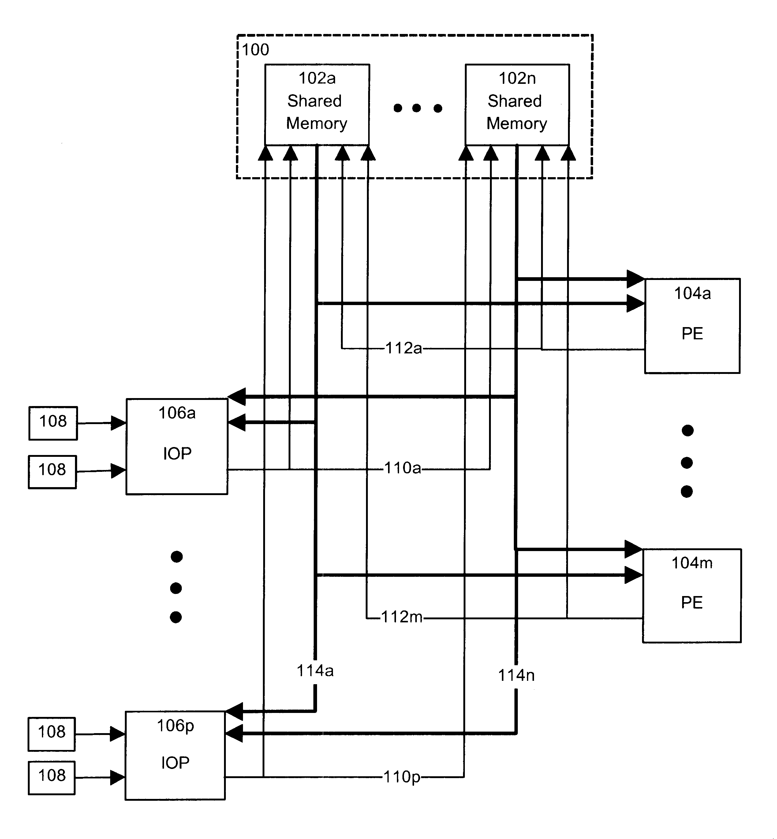
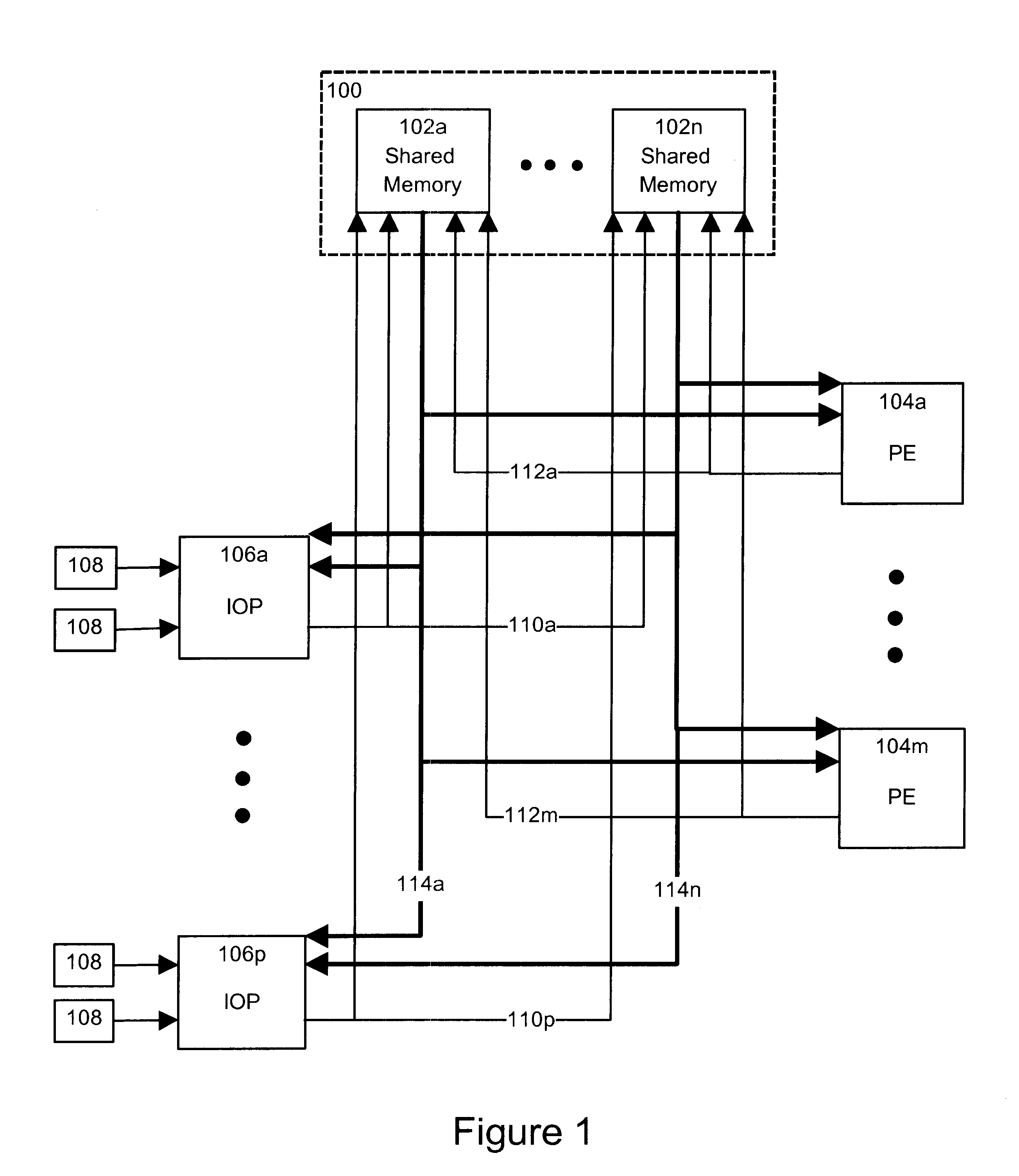
FIG. 1 illustrates the architecture of a multiprocessor, shared memory computing system in accordance with a preferred embodiment of the present invention. The system comprises shared memory 100, which in turn comprises a plurality of shared memory modules 102a to 102n (collectively and individually referred to as 102). Interconnected with shared memory 100 are a plurality of processing elements (PEs) 104a to 104m (collectively and individually referred to as 104) and a plurality of input / output processors (IOPs) 106a to 106p (collectively and individually referred to as 106). Connected to each IOP 106 is one or more input / output peripherals 108. Such peripherals may include disk and tape storage devices or communications interfaces such as OC3 interfaces.

The architecture of the multiprocessor system shown in FIG. 1 allows scalable processing using one or any other number of PEs 104, up to the limit of physically available slots. The system may be reconfigured simply by inserting a ...


PUM


Abstract

The present invention relates to a queuing system, implemented in the memory of a computer by the execution of a program element. The queuing system includes a queue with a plurality of memory slots, a write pointer and a read pointer. The write pointer permits to enqueue data elements in successive memory slots of the queue. The read pointer permits to dequeue data elements from the queue memory slots for processing, where these data elements are potentially non-dequeuable. Upon identifying a non-dequeuable data element in a particular memory slot of the queue, the read pointer is capable to skip over the particular memory slot and move on to a successive memory slot.

Description

The present invention relates to the field of multiprocessing in a shared memory computer architecture, particularly for performing Input / Output (IO) applications. specifically, it pertains to a method for interfacing transactional and non-transactional IO systems in the multiprocessing environment.Within the ever evolving world of computer systems, a particular change has arisen with respect to the design of better and faster systems. Originally, systems were implemented in a uni-processor environment, whereby a single Central Processing Unit (CPU), hereafter referred to as processor, was responsible for all computer performance, including computations and IO. Unfortunately, uni-processor designs have built-in bottlenecks, where the address and data buses restrict data transfer to a one-at-a-time trickle of traffic, and the system program counter forces instructions to be executed in strict sequence. Rather than designing better, faster uni-processor machines which will never overc...

Claims


Application Information

Patent Timeline
IPC IPC(8): G06F12/06G06F13/14G06F13/20G06F9/46
CPCG06F9/466G06F9/546G06F9/544G06F2209/548
Inventor LANTEIGNE, STEPHENLEWIS, DAVID
Owner RPX CLEARINGHOUSE
Learn More