Eureka AIR delivers breakthrough ideas for toughest innovation challenges, trusted by R&D personnel around the world.

Method and apparatus for imaging a field of regard by scanning the field of view of an imaging electro-optical system in a series of conical arcs to compensate for image rotation

Inactive Publication Date: 2003-04-29
NORTHROP GRUMMAN INNOVATION SYST INC
View PDF6 Cites 28 Cited by
  • Summary
  • Abstract
  • Description
  • Claims
  • Application Information

AI Technical Summary

Problems solved by technology

The main disadvantage of a spinning satellite is that it only allows the imager to view the Earth's surface for less than 5% of its total duty cycle.
This phenomenon, known as image rotation, is an intrinsic problem in a two-axis scanning system that uses a single scan mirror in object space.
This is a disadvantage of the prior art because it precludes use of a resolution enhancing technique known as Time Delay and Integration (TDI).
Another problem with the prior art has to do with how errors are inherently introduced across each scan line by variations in emissivity of the scan mirror.
Unfortunately, the emissivity of the GOES imager's scan mirror varies as a function of the angle of incidence and this angle of incidence varies by about 9.5.degree. on each scan line.
Also, the outer gimbal axis cannot be a principal axis of the system for all mirror angles unless the mirror motion is compensated by a counter-rotating mass.
Since highly accurate pointing is required, it is difficult to implement the necessary scan pattern by simultaneous rotations about both axes during the active portion of the scan.
Shading of IR images is particularly hard to correct because the observed radiance has a component that varies with both the temperature of the scan mirror and its reflection angle.
Since the RMS blur induced by this mis-match is less than 5% of one pixel, it is a small source of image quality degradation.
Therefore, variation in the reflection angle within a scan line is more troublesome that variation in the reflection angle from line to line.
Therefore, the worst-case results are probably unduly pessimistic.
If the FPA's are all parallel to the z-axis in the focal plane, then those FPA's for which B is non-zero will require staggered sampling (like the visible arrays in the GOES Imager) which would be difficult to implement in an array using TDI.

Method used


Image

  • Method and apparatus for imaging a field of regard by scanning the field of view of an imaging electro-optical system in a series of conical arcs to compensate for image rotation
  • Method and apparatus for imaging a field of regard by scanning the field of view of an imaging electro-optical system in a series of conical arcs to compensate for image rotation
  • Method and apparatus for imaging a field of regard by scanning the field of view of an imaging electro-optical system in a series of conical arcs to compensate for image rotation

Examples


Embodiment Construction

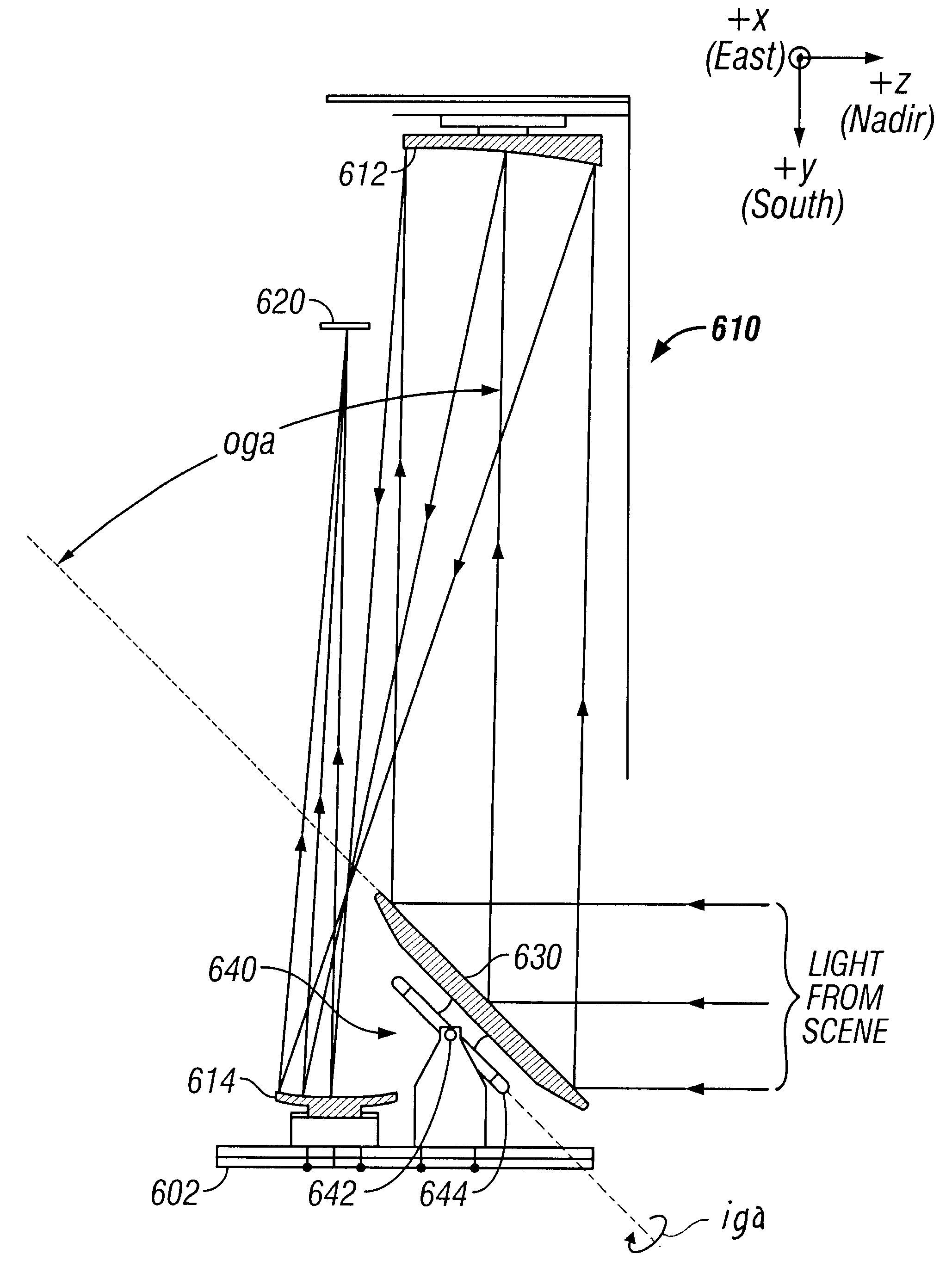
geosynchronous imager according to the present invention has been designed to satisfy two sets of requirements: those for a next-generation operational weather imager and those for a geostationary scientific instrument. It is to be mounted on a three-axis stabilized geostationary satellite. It has 18 spectral channels ranging from 0.47 to 13.3 .mu.m. It scans the full Earth disk, from geosynchronous orbit, in less than 15 minutes while simultaneously scanning smaller frames at higher rates. To achieve the required coverage rate, the exemplary geosynchronous imager scans with long linear arrays that subtend 0.8.degree.. It has a plane scan mirror in object space, mounted on a two-axis gimbal system, followed by a three-mirror, off-axis, all-reflective telescope. Dichroic beam splitters allow the geosynchronous imager to have four co-registered focal planes in four different wavelength bands, each of which has several linear focal plane arrays (FPA's) that are scanned sequentially ove...


PUM


Abstract

A two-dimensional field of regard is scanned with a single plane mirror in the object space of a telescope, maintaining a fixed relationship between the rotational direction of scan and the projection of the telescope's focal plane. The two dimensional field of regard is covered by a series of conical arcs, each arc being scanned by rotation at constant angular velocity about the inner axis of the two-axis system. This scanning system accommodates applications such as TDI that require an opto-mechanical scan with a constant linear velocity (magnitude and direction) in the focal plane. Shading of IR images is mitigated by calibration at the ends of each scan line and by a scan geometry that minimizes changes in reflection angle.

Description

1. Field of the InventionThe present invention relates generally to the field of imaging a two-dimensional field of regard. More particularly, the present invention relates to imaging of the full-Earth disk by a spacecraft that scans the field of view of an imager across the full Earth disk.2. Background InformationOne of the most common uses for artificial planetary satellites is to produce images of the planet's surface. Many Earth-orbiting satellites capture images of Earth for purposes ranging from military intelligence to weather forecasting. Orbital imaging for weather forecasting and for scientific purposes demands images of vast areas of the Earth at once.It is common to image a planet (e.g., Earth) from space using an imaging electro-optical sensor constructed from a telescope that collects radiation from a remote source and brings it to focus on one or more focal plane arrays (FPA's) with each FPA containing many detector elements. A scanning sensor moves the image of the ...

Claims


Application Information

Patent Timeline
IPC IPC(8): G01C11/02G01C11/00
CPCG01C11/02
Inventor BREMER, JAMES C.
Owner NORTHROP GRUMMAN INNOVATION SYST INC
Why Eureka
Eureka Blog
Learn More