
Fiber optic alignment system and method

a fiber optic and alignment system technology, applied in the direction of instruments, liquid/fluent solid measurement, investigating moving fluids/granular solids, etc., can solve the problem of excessively delicate alignment requirements to achieve this

Inactive Publication Date: 2003-04-08
BLAKE JAMES N +1
View PDF2 Cites 17 Cited by
  • Summary
  • Abstract
  • Description
  • Claims
  • Application Information

AI Technical Summary

Benefits of technology

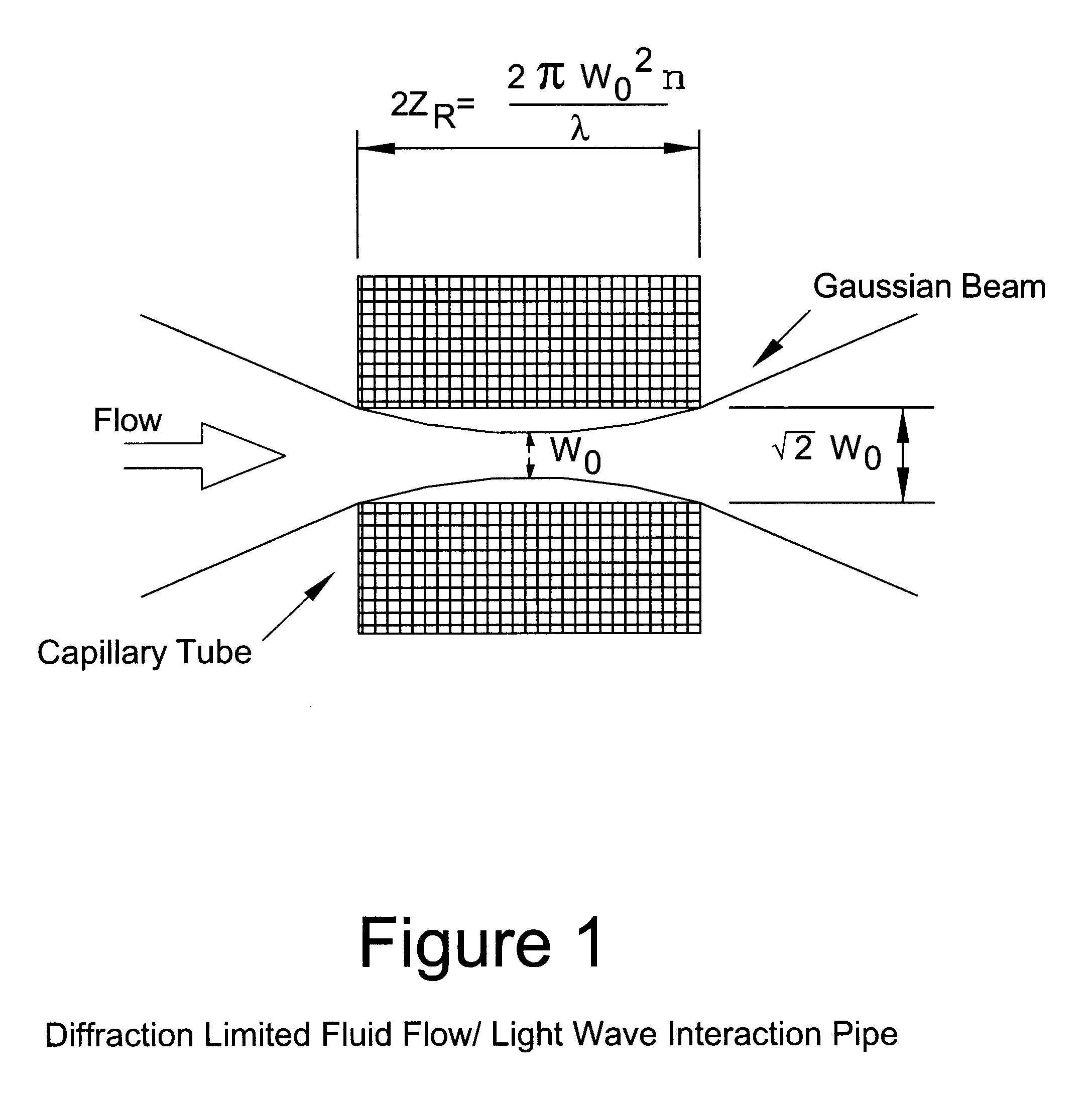
In this Part, we discuss the application of a Sagnac interferometer for measuring velocities of a moving medium. A moving medium "drags" the light propagating through it and the phrase velocity of the light depends on the direction of light propagation relative to the velocity of the material. This effect is called the Fresnel drag and represents the basic principle of the flow meter. The drag coefficient depends upon the refractive index of the material and is bigger for a more optically dense medium. Using a modifier Sagnac Interferometer we can arrange a system where the two counter-propagating light waves travel through a moving material obtaining a phase difference proportional to the velocity of the media. Because of the intrinsic reciprocity of a Sagnac interferometer, this phase shift is observed only in the presence of a flow, which makes it possible to realize an optical flow meter having an ultimately high sensitivity. We realized such a Sagnac interferometer based Fresnel drag fluid flow meter capable of detecting extremely small flow rates by using a near diffraction limited flow / light wave interaction pipe. An optimized design of the pipe along with the use of a state-of-the-art Sagnac interferometer results in a minimum detectable water flow rate of 1 drop per 5 hours. The flow meter's capability of measuring the water consumption by a small plant in real time has been demonstrated. We then designed an automated alignment system which finds and maintains the optimum fiber coupling regime, which makes the applications of the Fresnel drag based flow meters practical, especially if the length of the interaction pipe is big. Furthermore, we have applied the automatic alignment technique to an air flow meter, in order to guide the light through a long air flow / light interaction pipe, while automatically maintaining the optimum alignment. The use of the automatic alignment systems in the coherent domain reflectometry is believed to enhance the resolution of the reflectometry by increasing the length of the continuous scan.
It follows from this equation that if we change the distance between the fiber tips while maintaining the alignment at the same time, the gain will vary which may lead to the instability of the servo lock. In order to prevent that, an automatic gain control circuit needs to be designed. This is particularly important for the applications of the alignment system used for the coherent domain reflectometry, where in order to achieve a high resolution, the distance from the fiber tip to the detector set is to be changed significantly. This system will be described later in the Part. The position of the fiber on the left is controlled by the detectors on the aperture on the right, while the position of the fiber on the right is controlled by the detectors on the aperture on the left. To maintain the alignment in the Z direction the total intensity on all the detectors is to be kept constant. This, on the other hand, leads to a lossy system, because some amount of light has to be cut by the photo diode aperture at the front of the lens, so that the servo system obtains the error signal and locks the position of the fiber tops to maintain constant intensity on the detectors. For a given light / media interaction length, we can optimize the optical components, the PZT actuators and the loop electronics to achieve minimum optical losses and robust performance of the servo. Servo bandwidths of more than 10 kHz are readily achievable.

Problems solved by technology

The alignment requirements to accomplish this are excessively delicate especially when the interaction region is long.

Method used


Image

  • Fiber optic alignment system and method
  • Fiber optic alignment system and method
  • Fiber optic alignment system and method

Examples


Embodiment Construction

We start with the equation describing the Gaussian distribution of the fiber mode in the plane of the fiber facet.

E(r o.multidot.y.sup.o)=ea[(x.sup.o -to)2+(y.sup.o -yo)2] (A.1)

Before we apply the Fourier optics rules to calculate the field distributions at different distances z. as the light propagates, let us first check if we can apply the far field assumption, to our system. The field distribution E.sub.lens in the plane of the lens can be considered the far field if the distance from the fiber to the lens is greater than ##EQU8##

where .lambda. is the wavelength, and d is the diameter of the fiber core. For typical values used in practice, .lambda.=0.8 .mu.and d=10 .mu.m. this distance is equal to 0.4 mmm. which is much smaller that the local length of the lens f.about.5 mm. Therefore the distance from the fiber tip to the lens can be considered as the far field and the field distribution on the lens is the Fourier transform of the field described by equation. A1. The upper inde...


PUM


Abstract

A method and system for aligning optical fibers includes aperturing the optical beams from the optical fibers at two points along a path. Photodetectors are placed on the apertures and the positions of the tips of the optical fibers are controlled using actuators to center the optical beams within the apertures.

Description

This invention relates generally to fiber optics, and particularly, to a fiber optic alignment system and method.In a 1993 a paper entitled "A Fresnel Drag Flow Meter," written by R. deCarvalho and J. Blake of Texas A&M University, and W. Sorin of Hewlitt Packard Laboratories, a new method of measuring fluid flow using a fiber optic Sagnac interferometer was described [1]. The principle of operation is that light travels faster with a flowing material than against it. A Sagnac interferometer was used to measure the time difference it took for light to travel around a closed loop, part of which contained the flowing material.Two problems were found to exist in this flow meter which had to be overcome in order for it to become practical. First, the light has to be taken out of the optical fiber and passed as an optical beam through the flowing material. Then this light has to be refocused back into the optical fiber. The alignment requirements to accomplish this are excessively delica...

Claims


Application Information

Patent Timeline
Patent Type & Authority Patents(United States)
IPC IPC(8): G01F1/66G01B11/27
CPCG01F1/661G01B11/272
Inventor BLAKE, JAMES N.TSELIKOV, ALEXANDER A.
Owner BLAKE JAMES N
Learn More