Eureka AIR delivers breakthrough ideas for toughest innovation challenges, trusted by R&D personnel around the world.

Dispersion shifted optical fiber having triple clad

a technology of optical fiber and clad, applied in the field of optical fibers with triple clad, can solve the problems of unsatisfactory non-linear effects, increase of undesirable bending loss, distortion of light signal, etc., and achieve the effects of suppressing non-linear effects, reducing bending loss, and large effective area

Inactive Publication Date: 2003-02-04
LG CABLE LTD (KR)
View PDF19 Cites 6 Cited by
  • Summary
  • Abstract
  • Description
  • Claims
  • Application Information

AI Technical Summary

Benefits of technology

In addition, it is the object of the present invention to provide the optical fiber that has an effective area equal to or larger than 60 .mu.m.sup.2 along with the decreased bending loss.
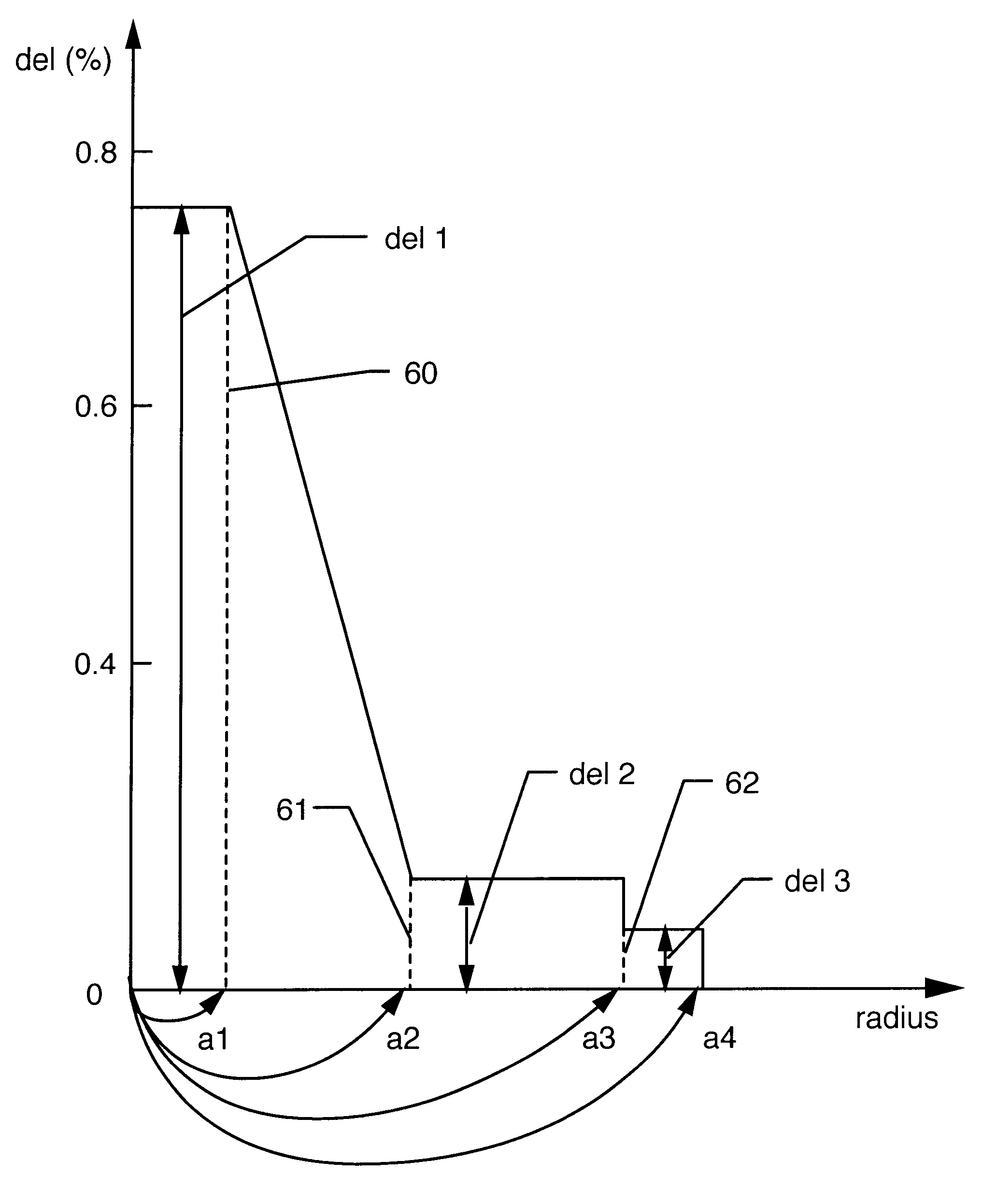
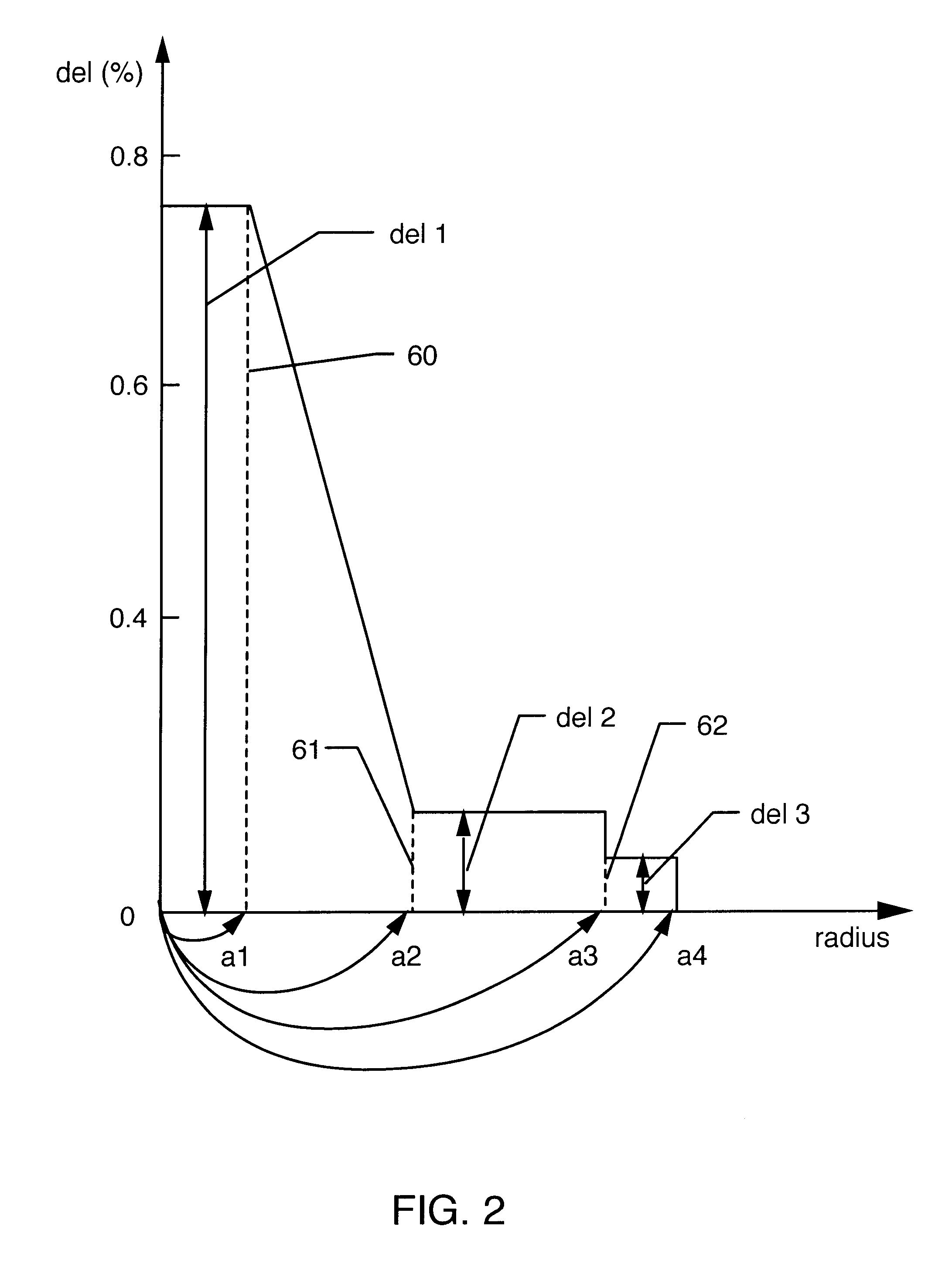
Thus, when the a3 / a4 lies in the range of 0.5 to 0.8 and the del2(%)-del3(%) lies in the range of 0.04% to 0.06%, the optical fiber according to the present invention can have a large effective area of 60-70 .mu.m.sup.2, the bending loss of 0.015 dB or less and the dispersion of 2-4 ps / nm-km at the wavelength of 1550 nm which makes it possible to suppress the non-linear effects.

Problems solved by technology

The wavelength division multiplexing method contributes to the increased transmission capacity but causes undesirable non-linear effects that have serious influence on transmission characteristics of the optical fiber.
The increase of the effective area, however, results in the increase of the undesirable bending loss.
Among non-linear effect, four wave mixing creates light having a new wavelength from the interference between lights having different wavelengths, thereby causing the distortion of light signal.
However, the optical fiber having this design has a problem caused from the large refractive index difference between the core and the clad: the light concentrates on the core because of the large index difference, and, therefore, the optical fiber can accomplish the decreased bending loss but has the decreased effective area.
Such distribution of the refractive index results in increasing the effective area and, at the same time, causes the bending loss to increase because the light spreads through various portions.
Thus, the above-mentioned optical fiber can provide the large effective area but still has a problem of the increased bending loss.

Method used


Image

  • Dispersion shifted optical fiber having triple clad
  • Dispersion shifted optical fiber having triple clad
  • Dispersion shifted optical fiber having triple clad

Examples


example 2

The present example corresponds to the optical fiber design as shown in FIG. 3. In the present example, the refractive index (n1) of the first core (22) is gradually increased from the initial value (n0) over its radius (a1) as shown in the FIG. 3. Unlike the Example 1, the present example is designed taking a center dip that occurs during MCVD (modified chemical vapor deposition) process into consideration.

In the present example, the inventors of the present invention intended to implement the optical fiber, which has the dispersion of 2.5-3.5 ps / nm-km at the wavelength of 1550 nm, the effective area of 60-65 .mu.m.sup.2, and the 32 mm.psi. bending loss of 0.02 dB or less. The inventors performed a number of simulations by using the numerical method known in the optical fiber design field.

During the simulations, the inventors of the present invention set the ranges of the radii (a1, a2) of the first and second cores (22, 24) as 0.85.+-.0.15 .mu.m and 2.7.+-.0.15 .mu.m respectively....


PUM


Abstract

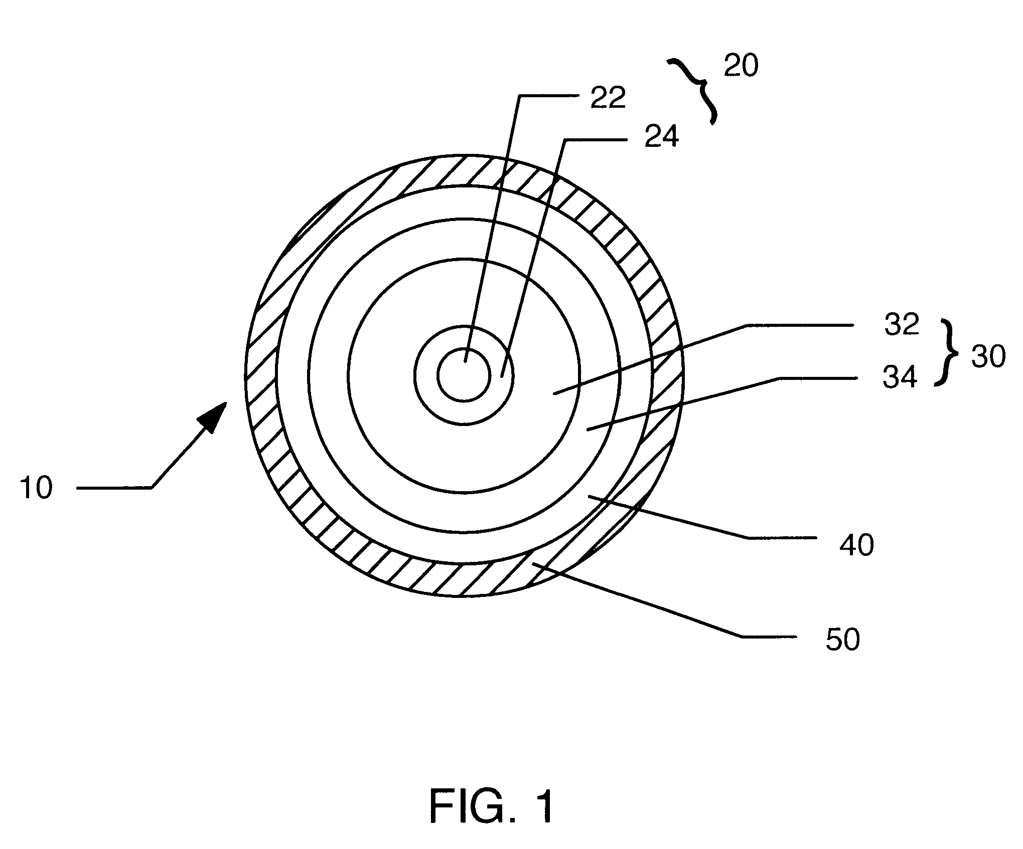
The present invention is related to a dispersion-shifted optical fiber for use in a wavelength division multiplexing system, which comprises a core, an inner clad, and a silica clad, wherein the optical fiber has a relatively low dispersion at a wavelength of 1550 nm, an effective area of 60 mum2 and small bending loss. The core consists of a first and a second core, wherein the core has a refractive index distribution. The inner clad consists of a first inner clad having a refractive index smaller than that of the second core and a second inner clad having a refractive index smaller than that of the second inner clad. A silica clad surrounds the inner clad and has a refractive index smaller than that of the second inner clad.

Description

The present invention relates to a dispersion shifted optical fiber and, more specifically, relates to a dispersion shifted optical fiber having a core, an inner clad, and a silica clad which is suitable for the use in wavelength division multiplexing system. In addition, the present invention relates to the dispersion shifted optical fiber which has a low dispersion at a wavelength of 1550 nm, and an effective area of 60 .mu.m.sup.2 or more without degradation in bending performance.The introduction of an optical amplifier in the field of optical communication system makes it possible for a wavelength division multiplexing method to be available. The wavelength division multiplexing method contributes to the increased transmission capacity but causes undesirable non-linear effects that have serious influence on transmission characteristics of the optical fiber. The non-linear effects results from a high power density, i.e., a high power per unit area. Thus, it is possible to reduce...

Claims


Application Information

Patent Timeline
IPC IPC(8): G02B6/02G02B6/028G02B6/00G02B6/036G02B6/36
CPCG02B6/02014G02B6/02271G02B6/03638G02B6/03611G02B6/0281G02B6/00
Inventor PARK, HYE YOUNGLEE, KWON MOOCHO, JOON HYUNG
Owner LG CABLE LTD (KR)
Why Eureka
Eureka Blog
Learn More