Method of apparatus for lifting and towing a load
a technology of lifting and towing a load and an apparatus, which is applied in the directions of transportation and packaging, transportation of items, salvaging damaged vehicles, etc., can solve the problem of large volume of pulling vehicles
- Summary
- Abstract
- Description
- Claims
- Application Information
AI Technical Summary
Benefits of technology
Problems solved by technology
Method used
Image

Examples
example 1
Mathematical Analysis of the Operation of Phase Two of the Invention
The operation of the invention is explained in mathematical terms in connection with FIGS. 21, 22, 23 and 24 which are schematic illustrations of the elements of the various cooperating structures and the related dimensional and angular relationships involved. FIG. 21 illustrates the positions of structures HBG, ABCD and RAJ before the lift and FIG. 23 illustrates the positions of structures HBG, ABCD and RAJ after the lift. The positions of structures HBG and ABCD change during the lift, but the position of structure RAJ does not change during the lift. Accordingly, structures HBG and ABCD are sometimes referred to as "moving" and structure RAJ is sometimes referred to as "stationary." FIG. 22 illustrates the positions of structures HBG, ABCD and RAJ in the special situation wherein line CD is parallel to Line RJ.
It is assumed for convenience, as shown in FIG. 21, that line HWTG of structure HBG and line RUYJ of st...
example 2
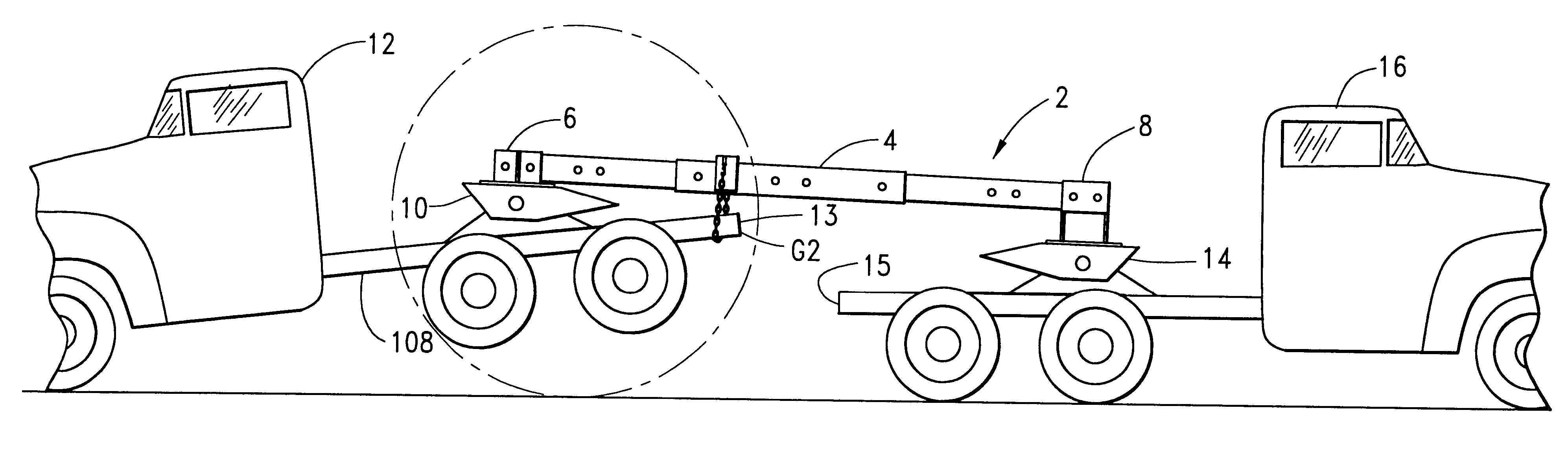
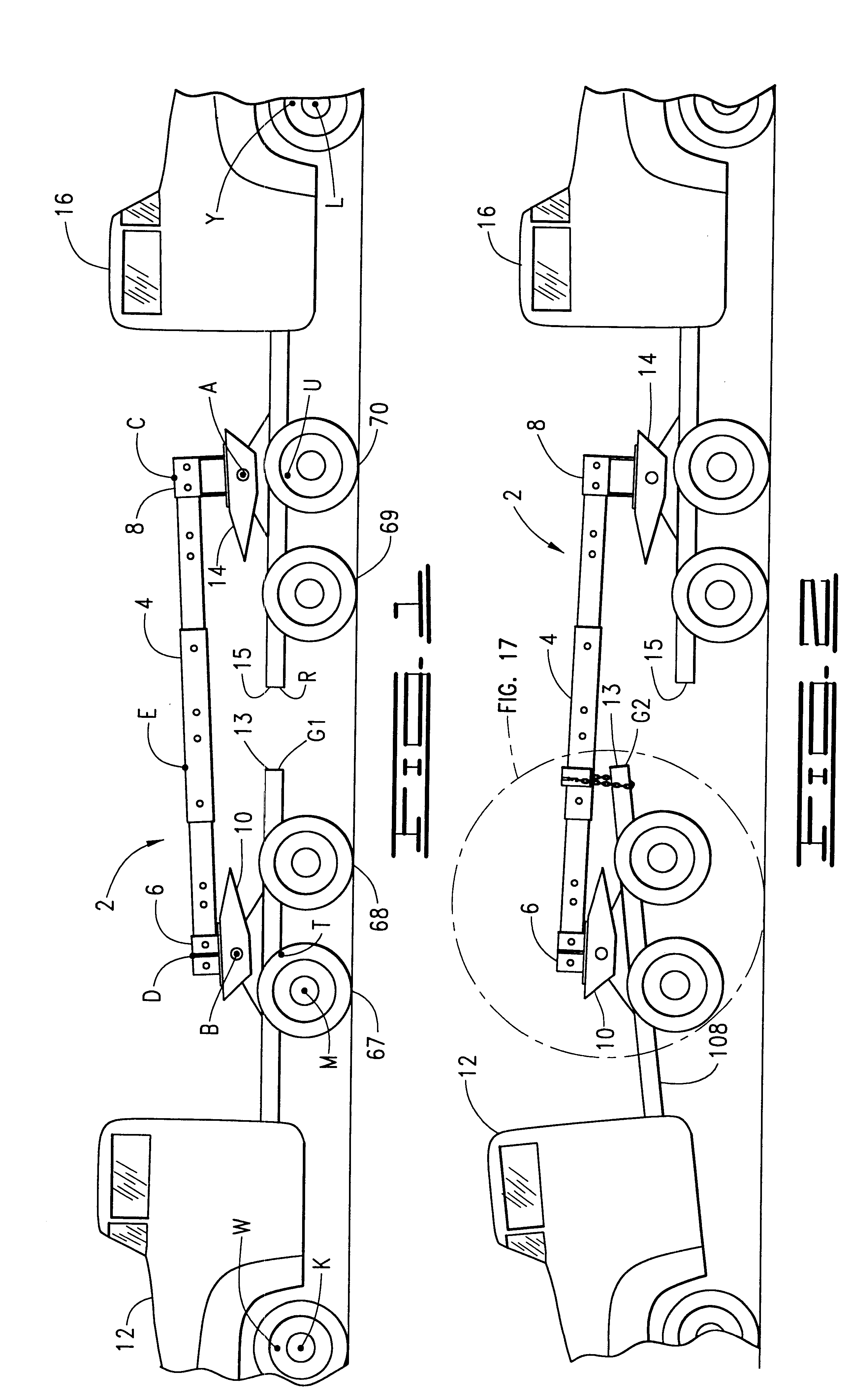
The program set forth in part G of Example 1, above, was employed to predict the vertical lift of hub M of vehicle 12 as shown in FIG. 1. According to current relevant official regulations the tread of the tire, as shown by reference numeral 67, on hub M must be raised a minimum of eight inches off the road surface before vehicle 12 may be pulled by vehicle 16.
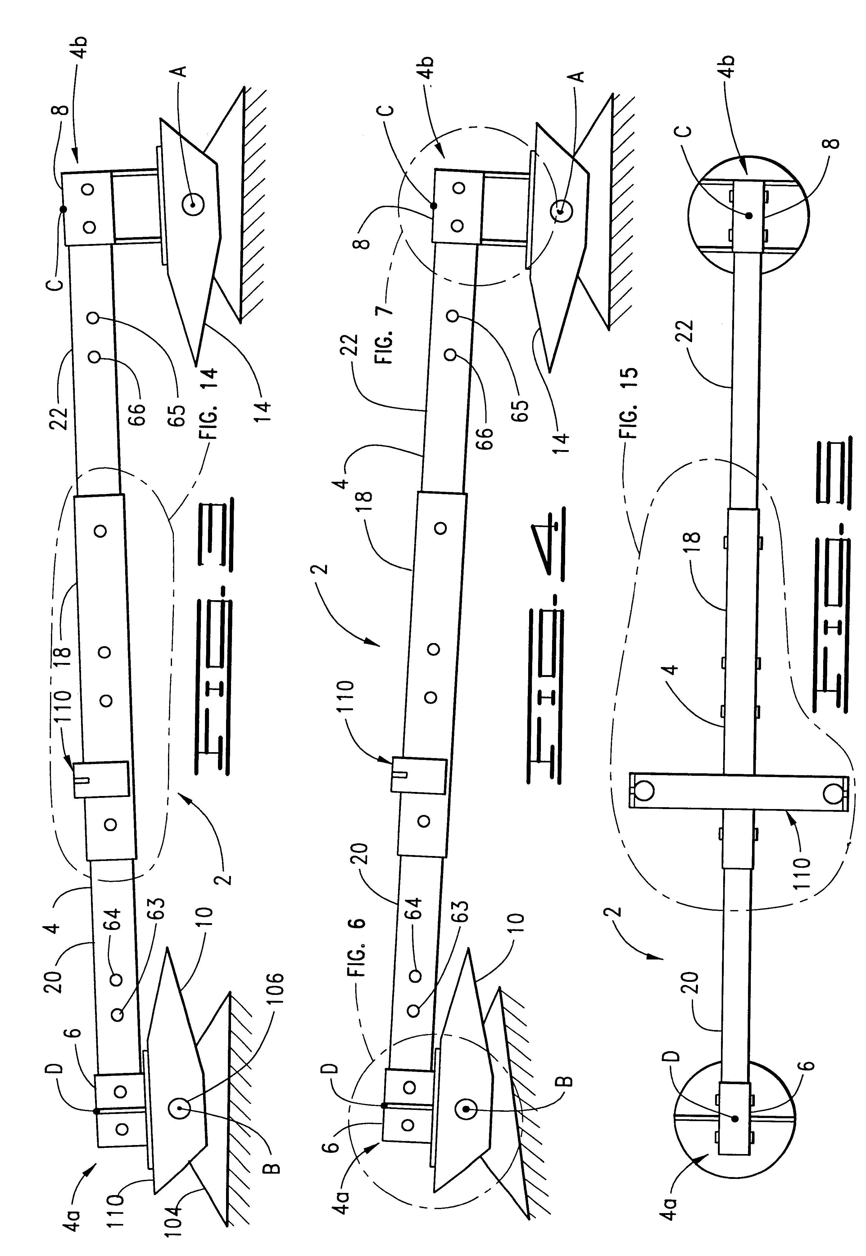
In this example vehicles 12 and 16 are large tractor trucks of the type referred to in the art as "semis." Vehicles 12 and 16 are connected by beam 2 as described above wherein center link 18 is a hollow steel member of rectangular cross section having a height of 8 inches, a width of 6 inches and a length of 60 inches. First end link 20 is a hollow steel member of rectangular cross section having a height of 7 inches, a width of 5 inches and a length of 72 inches. Second end link 22 is a hollow steel member of rectangular cross section having a height of 7 inches, a width of 5 inches and a length of 84 inches. It is evident t...
PUM
 Abstract
Description
Claims
Application Information
 - R&D
- Intellectual Property
- Life Sciences
- Materials
- Tech Scout
- Unparalleled Data Quality
- Higher Quality Content
- 60% Fewer Hallucinations
Browse by: Latest US Patents, China's latest patents, Technical Efficacy Thesaurus, Application Domain, Technology Topic, Popular Technical Reports.
© 2025 PatSnap. All rights reserved.Legal|Privacy policy|Modern Slavery Act Transparency Statement|Sitemap|About US| Contact US: help@patsnap.com