
Thin film write head with improved yoke to pole stitch

Inactive Publication Date: 2002-12-03
WESTERN DIGITAL TECH INC
View PDF14 Cites 160 Cited by
  • Summary
  • Abstract
  • Description
  • Claims
  • Application Information

AI Technical Summary

Benefits of technology

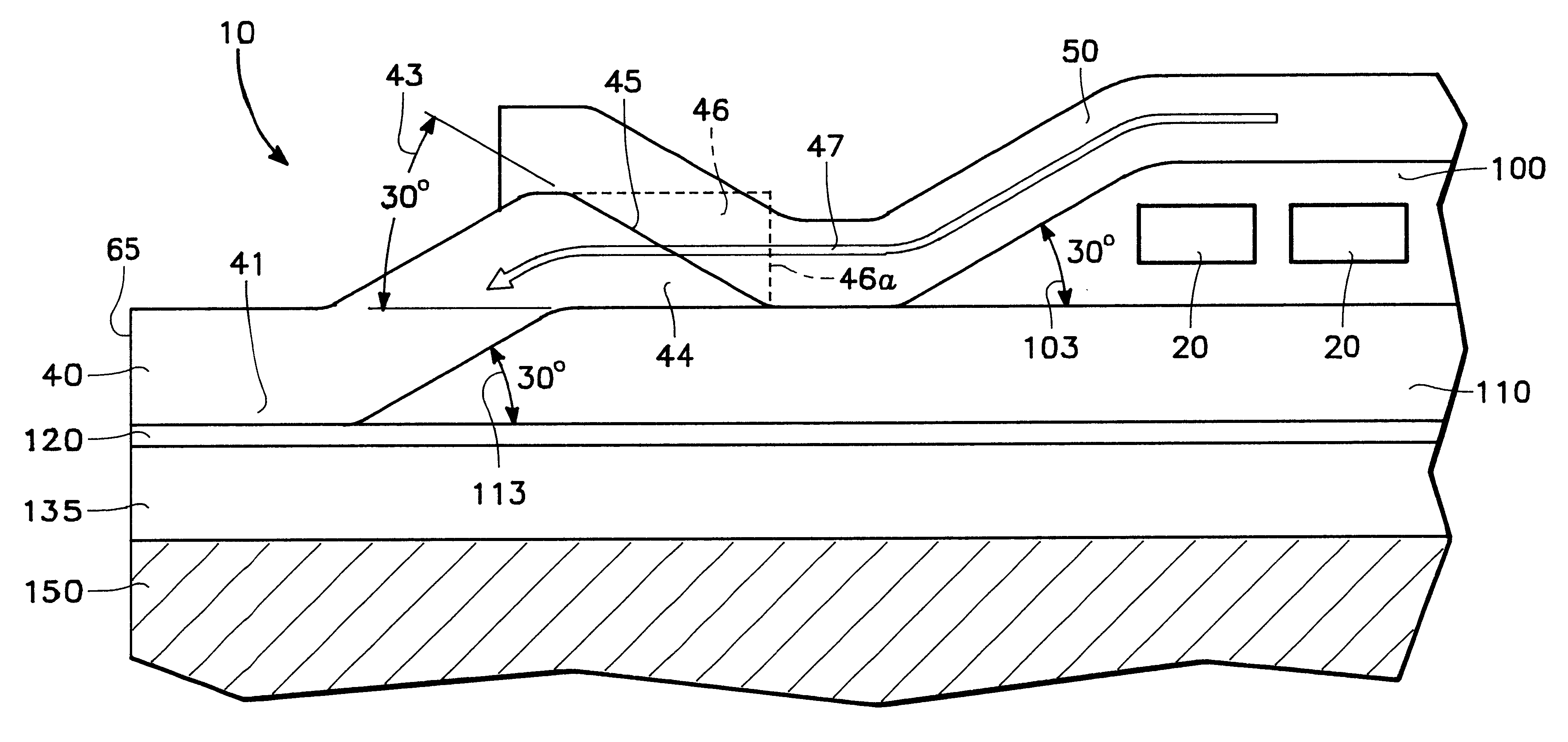
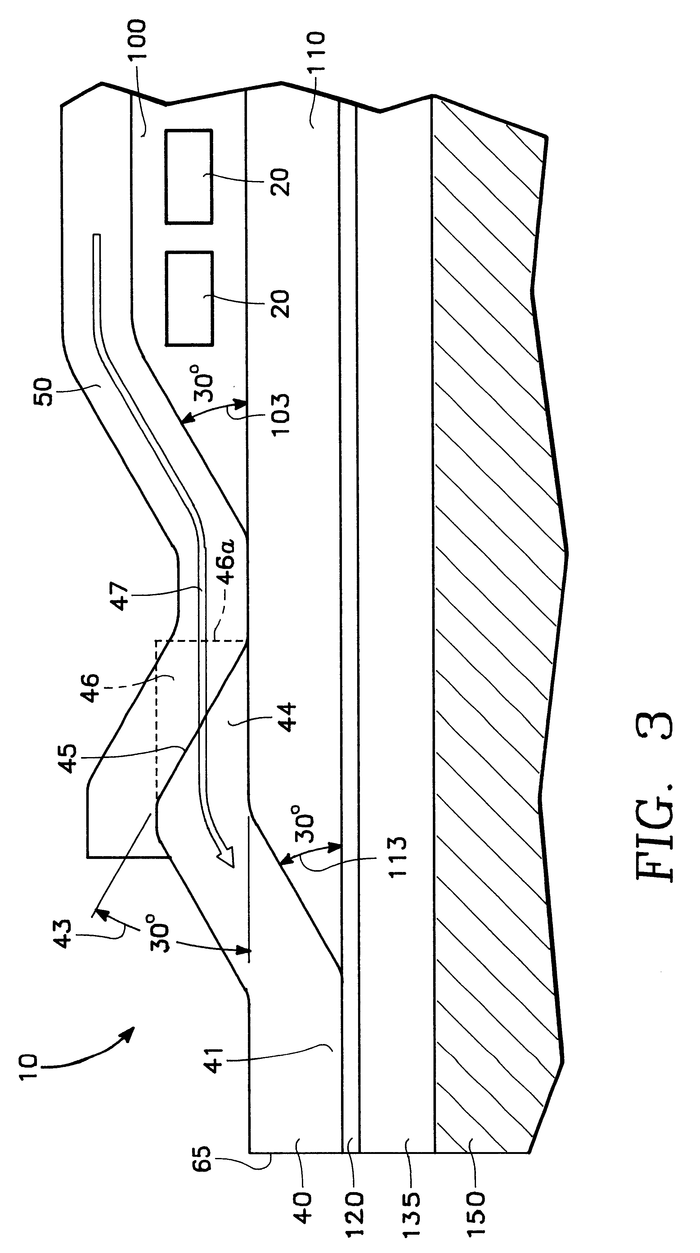
The sloping surface provides a shallow angle for depositing the yoke material over. The shallow angle improves the magnetic properties of the yoke material, particularly in the case of sputtered high moment magnetic materials, and improves the flux flow path through the yoke. As such, the present invention allows conductor coils to be located closer to the air bearing surface without sacrificing yoke material properties and flux flow.
An advantage of the present invention is that it allows the yoke and the yoke-to-pole tip stitch to be recessed from the air bearing surface, if desired, to prevent the yoke or yoke-to-pole stitch from inadvertently writing to the media.

Problems solved by technology

As ever smaller structures must handle higher magnetic flux, the write head structures, and in particular the yoke structure, become susceptible to saturation.
A problem with high magnetic moment material is that imperfections in the uniformity of the material can cause the permeability of the material to degrade.
One problem with forming the stitch along the air bearing surface is that, in addition to the primary write gap which is formed to write data to the media, a second write gap could form at the yoke / pole tip interface.

Method used


Image

  • Thin film write head with improved yoke to pole stitch
  • Thin film write head with improved yoke to pole stitch
  • Thin film write head with improved yoke to pole stitch

Examples


Embodiment Construction

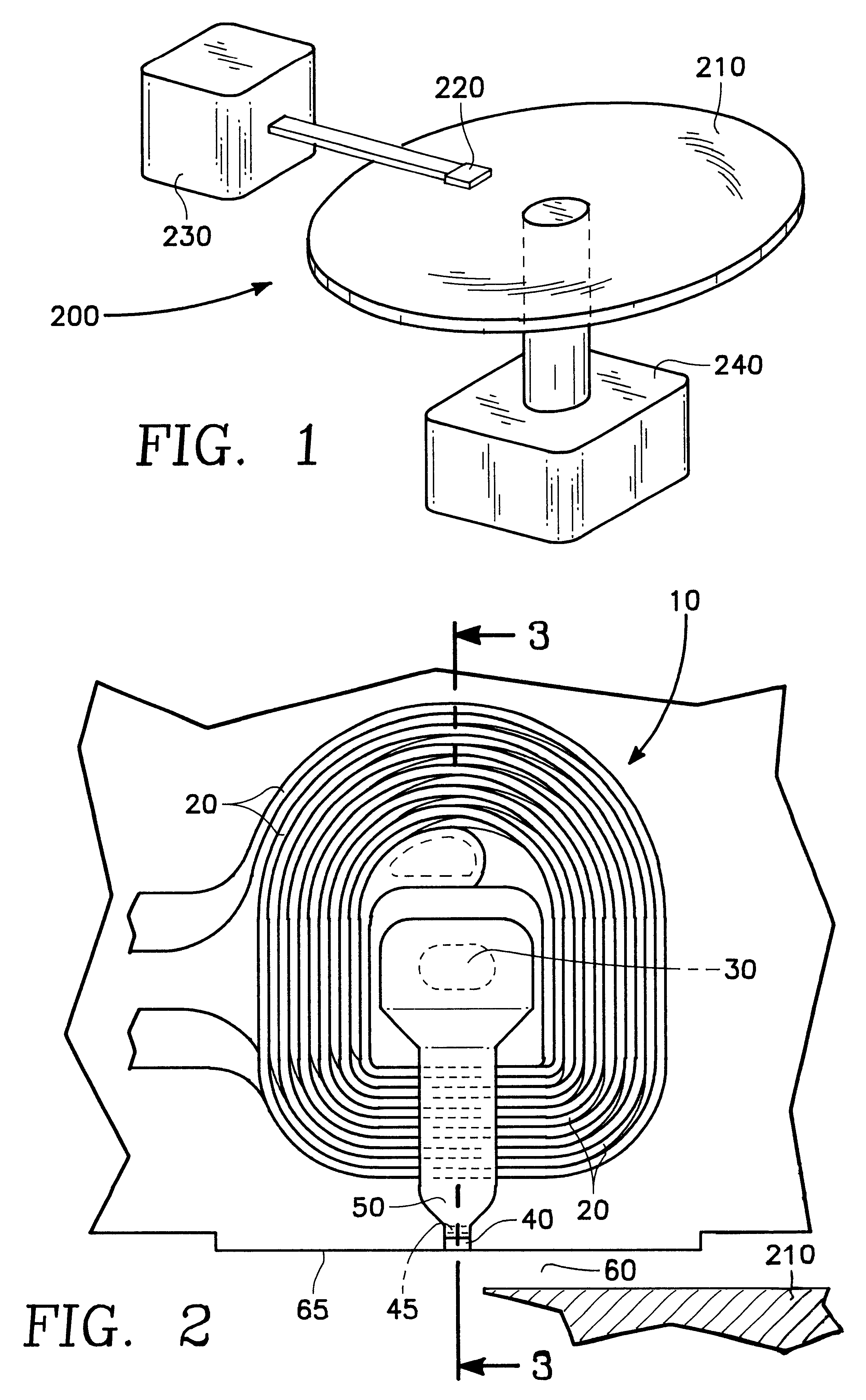
FIG. 1 shows the thin film write head of the present invention embodied in a disk type magnetic data storage and retrieval apparatus 200. The write head of the present invention is located within a merged head assembly 220 which rides above a magnetic storage media 210, depicted in FIG. 1 as a rotatable hard disk type storage media. The hard disk 210 is coupled to a motor 240 to provide rotation of the disk relative to the head assembly 220. An actuating means 230 may be used to position the head assembly 220 above the surface of the media 210 to read and write data in the form of magnetic bits from and to the media 210. The data storage and retrieval apparatus 200, typically has several hard disks 210 and several corresponding head assemblies 220.

FIG. 2 depicts a partial cut away of the top view of an embodiment of the structure of the thin film write head 10 of the present invention. Conductors 20 encircle a core 30 to produce magnetic flux in the core 30. The flux generated in th...


PUM


Abstract

The present invention provides an write head having an improved upper pole tip-to-yoke stitch. The upper pole tip is formed having an open faced sloping surface at an end of the pole tip distal from an air bearing surface. Preferably the angle of the sloping surface is about 30 degrees. The sloping surface provides a shallow angle for depositing the yoke material over which improves the magnetic properties of the yoke material, particularly in the case of sputtered high moment magnetic materials, and improves the flux flow path through the yoke. As such, the present invention allows conductor coils to be located closer to the air bearing surface without sacrificing yoke material properties and flux flow. The upper pole tip may have a back portion which is formed over an insulation layer located between a write gap layer and a conductor layer. Preferably the insulation layer and the conductor layer or layers are formed having sloping edges with shallow angles of about 30 degrees. An advantage of the present invention is that it allows the yoke and the yoke-to-pole tip stitch to be recessed from the air bearing surface, if desired, to prevent the yoke or yoke-to-pole stitch from inadvertently writing to the media.

Description

1. Technical FieldThe present invention relates to the field of thin film write heads.2. Background ArtData is stored on magnetic media by writing on the magnetic media using a write head. Magnetic media can be formed in any number of ways, such as tape, floppy diskette, and hard disk. Writing involves storing a data bit by utilizing magnetic flux to set the magnetic moment of a particular area on the magnetic media. The state of the magnetic moment is later read, using a read head, to retrieve the stored information.Data density is determined by the amount of data stored on an area of magnetic media and depends on how much area must be allocated to each bit. To decrease bit size, head size is decreased by fabricating thin film read and write heads. Thin film heads commonly employ separate write and read heads.Thin film write heads are typically formed by depositing and etching layers of magnetic, non-magnetic, dielectric, and electrically conductive materials to form the structures...

Claims


Application Information

Patent Timeline
IPC IPC(8): G11B5/31
CPCG11B5/3116G11B5/313G11B5/3146G11B5/3163
Inventor BARR, RONALD A.
Owner WESTERN DIGITAL TECH INC
Learn More