
Method and apparatus for a single upset (SEU) tolerant clock splitter

a clock splitter and upset technology, applied in the direction of generating/distributing signals, pulse techniques, instruments, etc., can solve the problems of introducing circuit disturbances, affecting the operation of clock splitters, and invalid results for 0.5-1.0 nanoseconds, etc., to achieve the effect of reducing the number of clock splitters

Inactive Publication Date: 2002-09-24
OL SECURITY LIABILITY CO
View PDF7 Cites 13 Cited by
  • Summary
  • Abstract
  • Description
  • Claims
  • Application Information

AI Technical Summary

Problems solved by technology

In a space-based environment, however, ionic strikes by sub-atomic cosmic particles are known to introduce circuit disturbances.
A single event upset occurring in the logic can cause an invalid result for 0.5-1.0 nanoseconds because this is a significant amount of time with respect to a pulse width.
Such an event occurring in a clock distribution chain causes a more widespread and potentially a much more serious result.
Such a false clock pulse can clock registers causing the registers to latch invalid data.
This can result in multiple uncorrectable multi-bit logic errors.
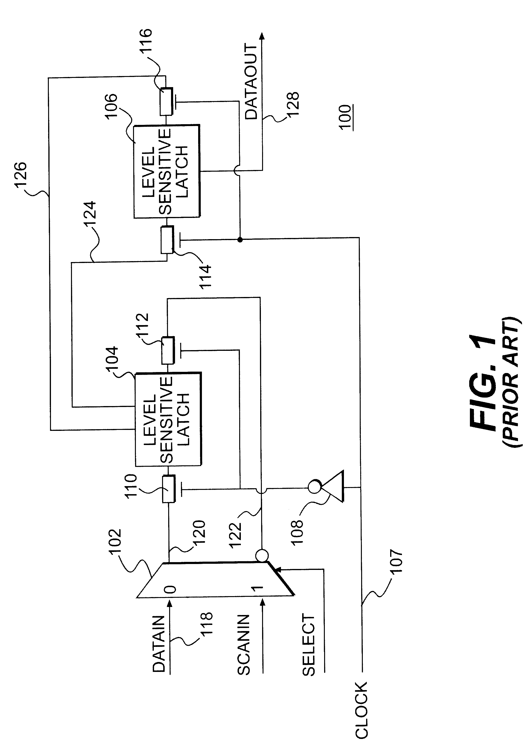
Unfortunately, an upsetting event occurring in the clock tree prior to clock signal 107 can cause a false clock pulse on clock signal 107.

Method used


Image

  • Method and apparatus for a single upset (SEU) tolerant clock splitter
  • Method and apparatus for a single upset (SEU) tolerant clock splitter
  • Method and apparatus for a single upset (SEU) tolerant clock splitter

Examples


Embodiment Construction

In the following detailed description of illustrative embodiments of the present invention, reference is made to the accompanying drawings which form a part hereof, and in which are shown by way of illustration specific illustrative embodiments in which the invention can be practiced. These embodiments are described in sufficient detail to enable those skilled in the art to practice the invention and it is to be understood that other embodiments can be used and that logical, mechanical and electrical changes can be made without departing from the spirit and scope of the present invention. The following detailed description is, therefore, not to be taken in a limiting sense.

The illustrative embodiments described herein concern electrical circuitry which uses voltage levels to represent binary logic states--namely, a "high" logic level and a "low" logic level. Further, electronic signals used by the various embodiments of the present invention are generally considered active when they...


PUM


Abstract

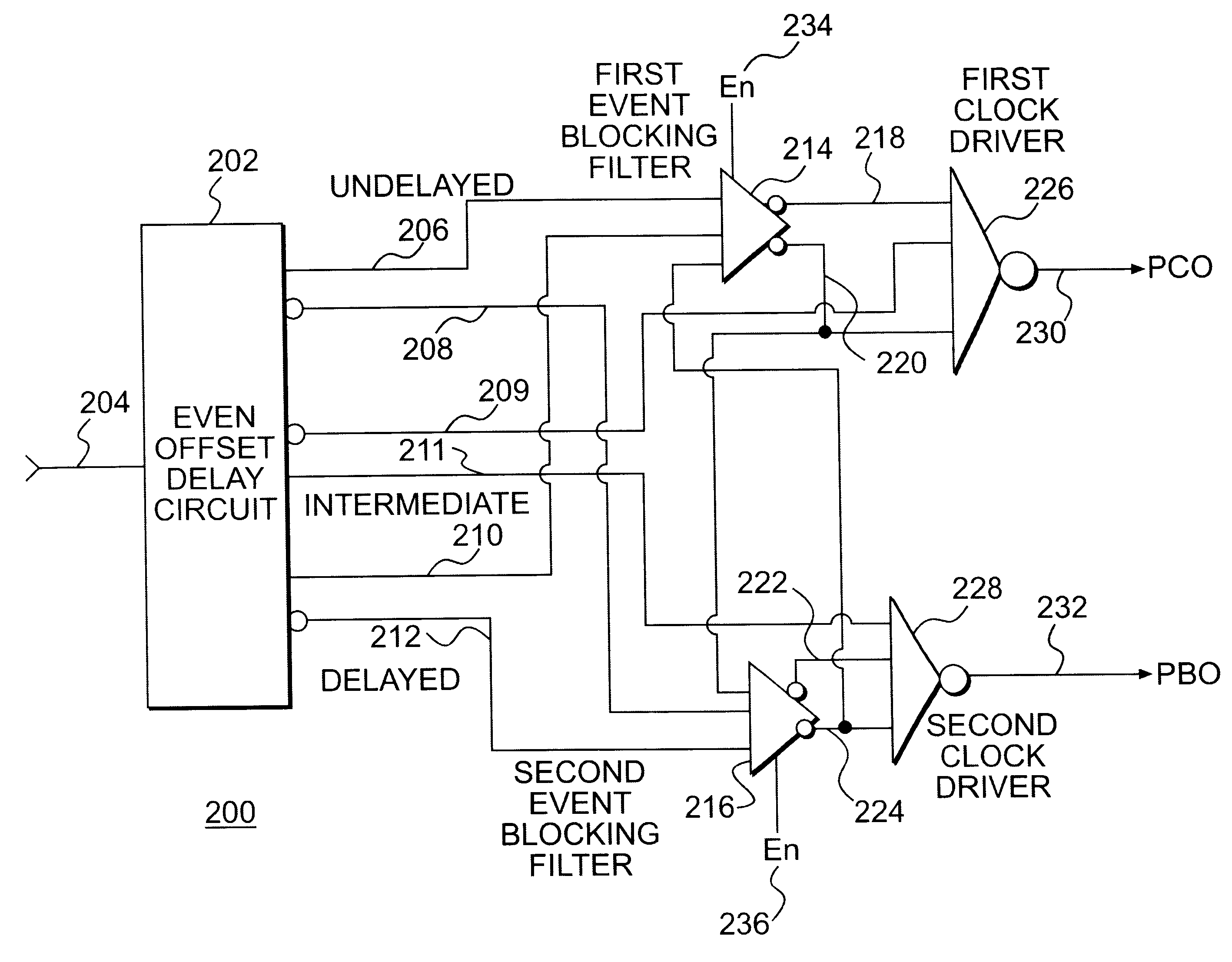
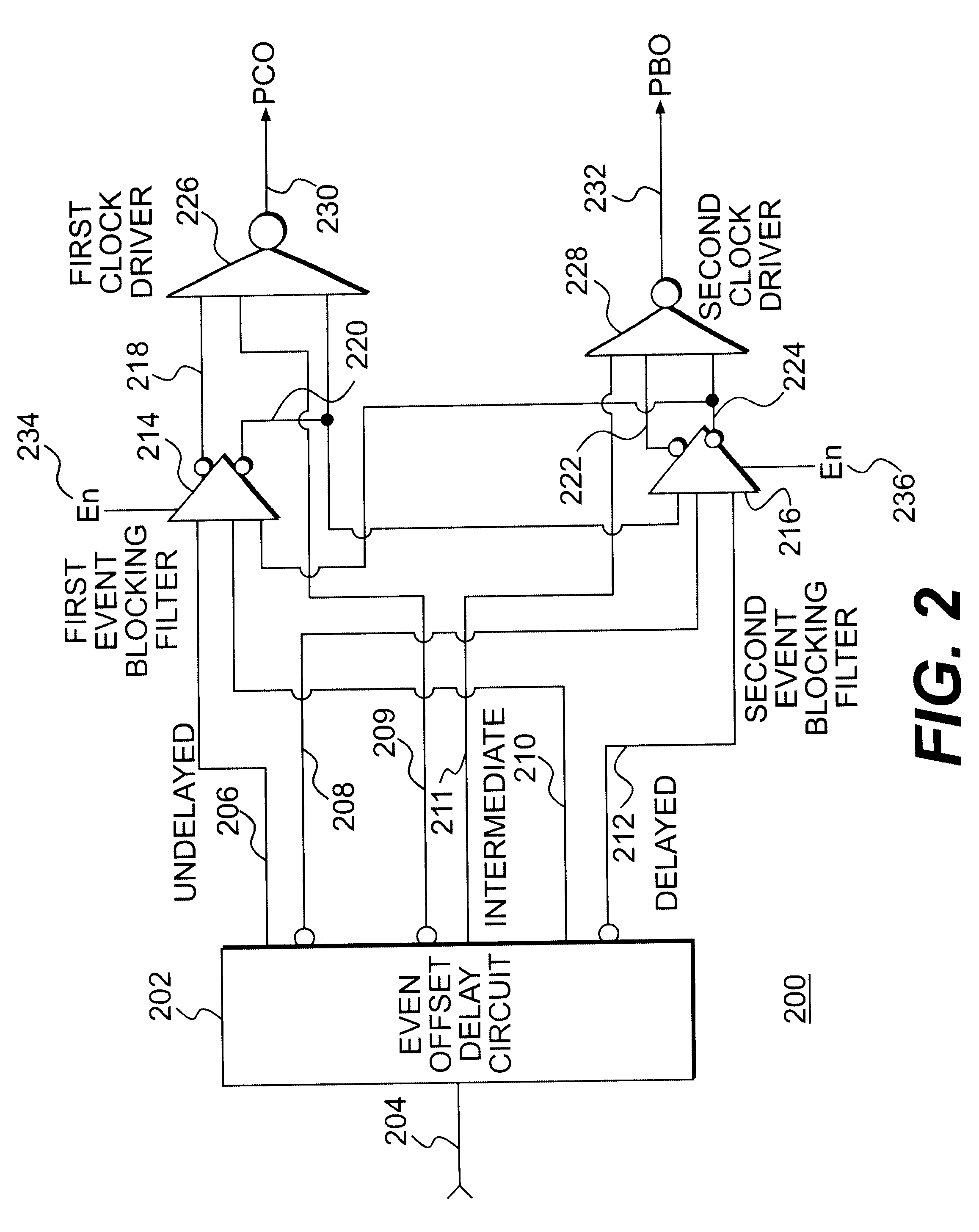
A clock splitter circuit for providing a single event upset (SEU) tolerant clock signal to latches in a space-based environment. The clock splitter circuit can include one or more event offset circuit delay circuits. The event offset delay receives a clock signal and generates a delayed clock signal. The event offset delay circuit can generate an inverted clock signal, a delayed inverted clock signal and a pair of intermediate clock signals. The delayed clock signal and inverted delayed clock signal can be delayed by the known duration of single event effects (SEE). The delayed and undelayed clock signals can be passed to an event blocking filter which can block any disturbance in the delayed and / or undelayed clock signals. A synchronizer can synchronize outputs of the event blocking filter prior to or coincident with being passed to corresponding inverting clock drivers. The synchronizers can also insure that the synchronized blocking filter outputs can not be low simultaneously. Intermediate clocks can also be provided corresponding to the inverting clock drivers. Outputs of the inverting clock driver can be a pair of SEU tolerant non-overlapping clock phase signals for driving one or more latches.

Description

1. Field of the InventionThe present invention is related to radiation hardened integrated circuits and, more particularly, to clock generation circuits for radiation hardened integrated circuits.2. Related ArtIncreasingly, space-based communication systems are including integrated circuits (IC) made in advanced deep sub-micron Field Effect Transistor (FET) technology. Typically, these ICs are in the insulated gate silicon technology commonly referred to as complementary metal oxide semiconductor (CMOS). CMOS ICs are advantageous in that they are high speed and low power. The CMOS ICs use little power compared to what other technologies require for comparable speed and function.In a space-based environment, however, ionic strikes by sub-atomic cosmic particles are known to introduce circuit disturbances. These circuit disturbances are known as single event effects (SEE) and, as single event upsets (SEU) when corrupting data in storage elements. Radiation hardened latches are well kn...

Claims


Application Information

Patent Timeline
IPC IPC(8): H03K5/15H03K5/151H03K5/1252H03K19/003H03K5/125G01R31/3185
CPCG01R31/318552H03K5/1252H03K5/1515H03K19/00338
Inventor YODER, JOSEPH W.KAZEMZADER, ABBAS
Owner OL SECURITY LIABILITY CO
Learn More