
Valve device for an internal combustion engine

a valve device and internal combustion engine technology, which is applied in the direction of non-mechanical valves, machines/engines, oscillatory slide valves, etc., can solve the problems of affecting the suction procedure and the exhaust procedure, and affecting the operation of the valve device. , the possibility of varying the time appears to be limited, and the construction is fairly complicated. , the effect of a plurality of further components

Inactive Publication Date: 2002-09-03
DAFAB
View PDF17 Cites 36 Cited by
  • Summary
  • Abstract
  • Description
  • Claims
  • Application Information

AI Technical Summary

Benefits of technology

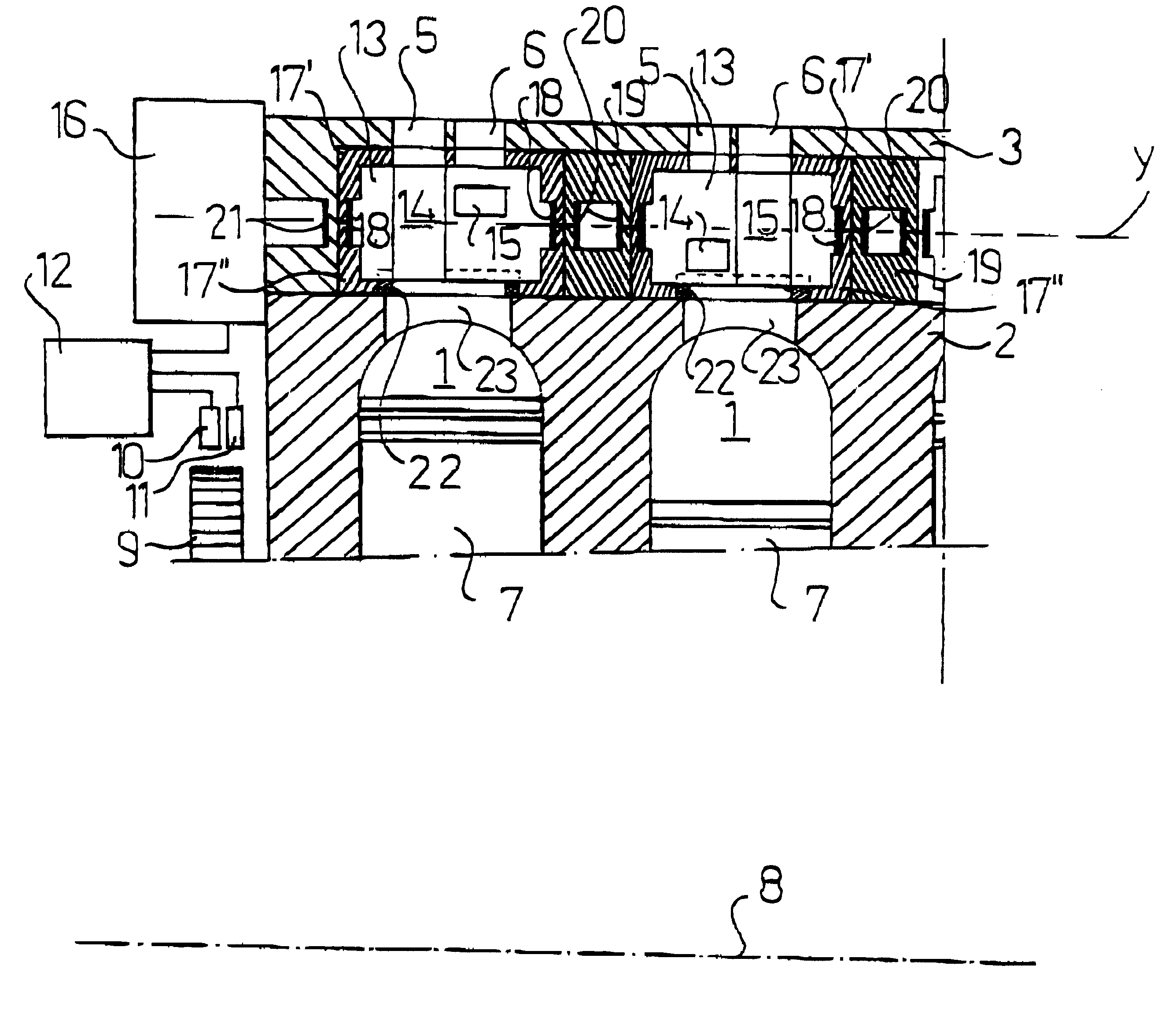
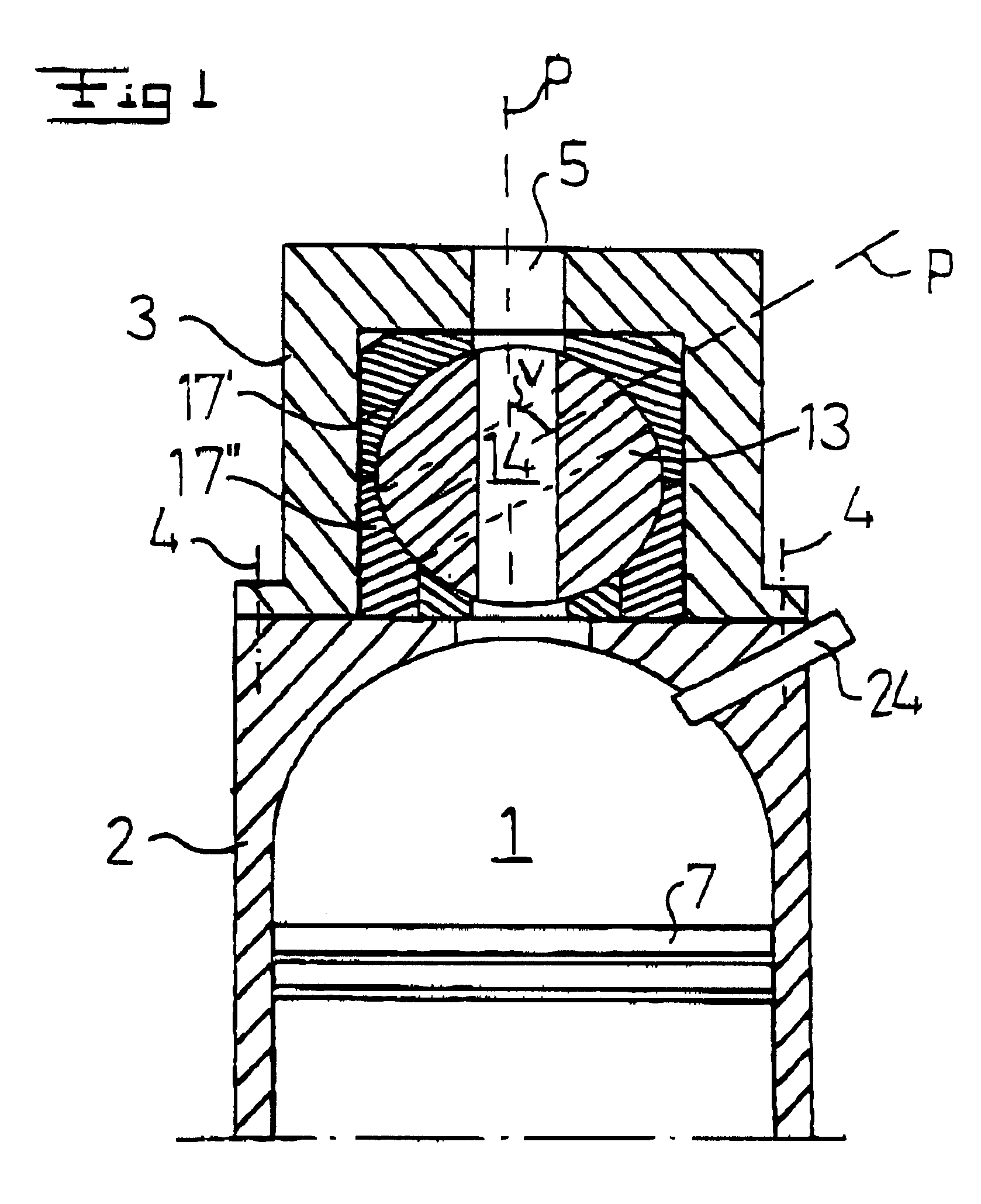
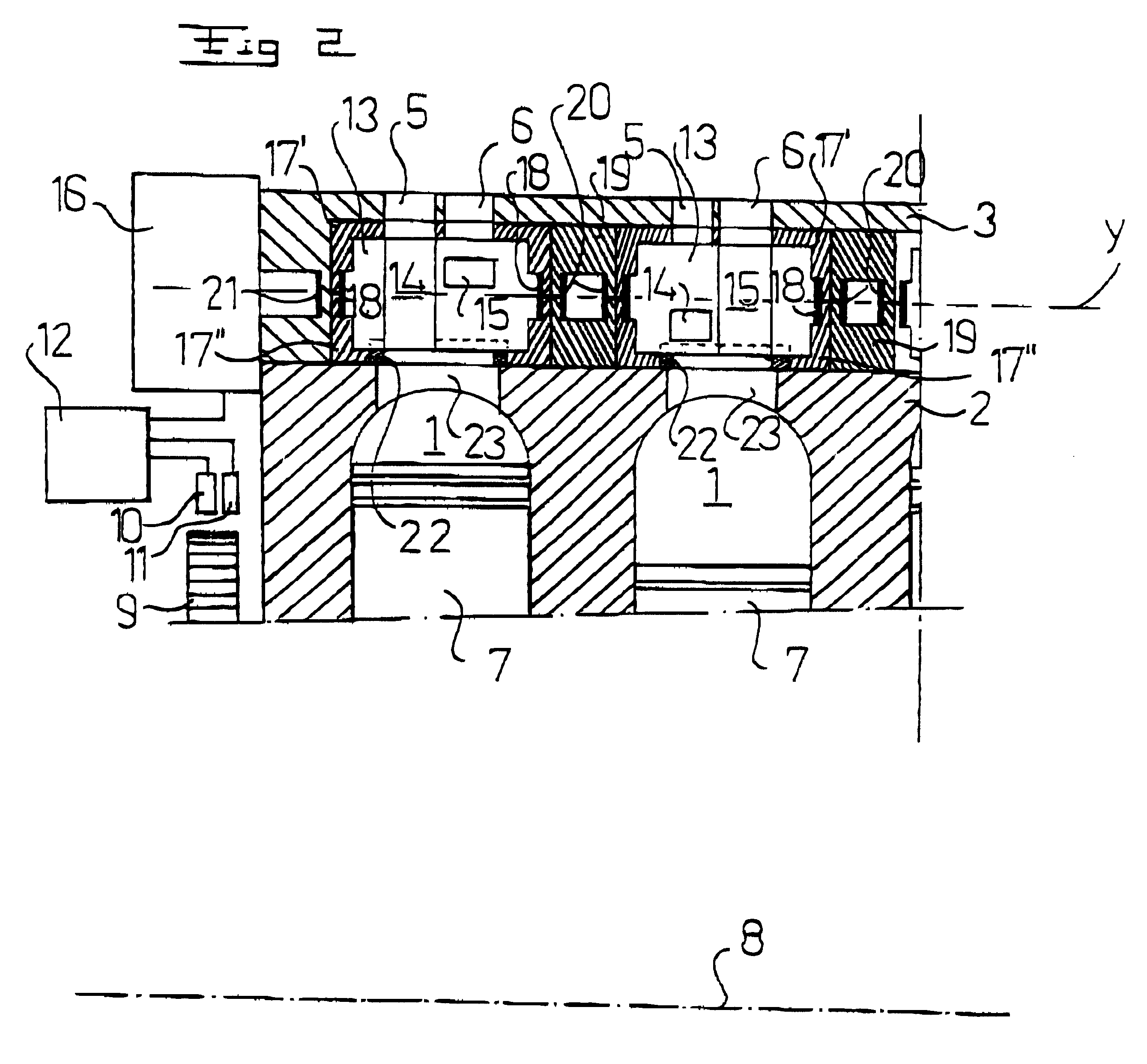
The present invention obtains this purpose by the initially defined valve device characterised by a rotary motor being separated from the combustion engine and being arranged to provide said rotation. Such a separate rotary motor may be driven independently of the rotation of the crank shaft, which permits the valve body to be discontinuously rotated. That is, the valve body is rotated at different speeds and thereby very fast during the opening or closing phase of the valve device. In this way it is possible to avoid a slowly successive opening and / or closing of the valve device. Furthermore, an advantage of such a rotating valve is that it merely needs to rotate one revolution, whereas the crank shaft rotates four revolutions, i.e. the wear may be kept on a low level. Furthermore, such a rotating valve has substantially fewer mechanical parts than conventional cam shaft controlled valves.
According to an embodiment of the invention, the rotary motor is consequently arranged to rotate the above mentioned valve body from one of its positions to an adjacent one of its positions by a first high rotation velocity, to then rotate the valve body from this adjacent position by a second low rotation velocity, and to rotate the valve body from this adjacent position to the next adjacent position. The first time period, during which the valve body rotates from one position to another, is consequently advantageously substantially shorter than the second time period during which the valve body rotates in a position. The actual position thus includes an interval and not only one single position. This means that an inlet channel may be kept completely open during substantially the whole suction stroke of the engine and an outlet valve may be kept substantially completely open during the exhaust stroke. The second low rotation velocity may be permitted to vary with the number of revolutions per time unit of the combustion engine in such a manner that, at a relatively low number of rounds, the second rotation velocity may be substantially zero, i.e. the valve body is essentially stationary. At a relatively high number of revolutions, the second low rotation velocity may have a low value above zero, i.e. the valve body may advantageously be permitted to rotate at a low velocity. This facilitates the achievement of a very high first velocity for moving the valve body from one of said positions to an adjacent position.
According to a further embodiment of the invention, a control unit is arranged to control the rotation of the rotary motor. Thereby, a first sensor member may be arranged to sense the position of a crank shaft of said combustion engine. It is thereby possible to control the rotation of the rotary motor by means of the control unit in response to the sensed crank shaft position. That is, the control unit may initiate a very quick rotation of the valve body at a certain crank shaft position in order to open an inlet valve, for instance, at the upper dead center, and control the rotary motor in such a way that it does not rotate during a certain angle interval. Where the combustion engine is a four-stroke engine, the first sensor member advantageously includes two sensors which are known per se, which enable an exact identification of the position of each piston with regard to the whole stroke, two revolutions of the crank shaft. Furthermore, a second sensor member may be arranged to sense the number of revolutions per time unit of the combustion engine, wherein the control unit is arranged to control the rotation of the rotary motor in response to the number of revolutions. In such a manner, it is easily possible to change the opening and closing time, respectively, of the valve body in response to the number of revolutions of the combustion engine. Furthermore, the control unit may be arranged to control the valve body in order to control the number of revolutions per time unit of the combustion engine. Thereby, it is possible to dispense with conventional throttles in the carburettor or with the air control in case of direct injection.
According to another embodiment of the invention, the first valve body is provided beside the second valve body, wherein their axes of rotation of the valve bodies are substantially parallel. Two rotating valves are consequently provided for each combustion chamber, i.e. one for the inlet valve and one for the outlet valve. The first valve body and the second valve body may advantageously be driven by a common rotary motor, wherein a transferring member having an input shaft and an output shaft, which do not coincide, may be arranged to transfer a movement of rotation of the rotary motor to at least one of these first and second valve bodies. Alternatively, the first valve body and the second valve body may be driven by a respective separate rotary motor. This creates possibilities for controlling the inlet valve and the outlet valve independently of each other; for instance the time for the opening of the inlet valve may be adjusted without influencing the time for the opening of the outlet valve. Thereby, the control unit may be arranged to control the phase position of one of the valve bodies in relation to the phase position of the other valve body in response to said number or rounds.
According to a further embodiment of the invention, the rotary motor includes an electric rotary motor. An electric motor may be controlled in an easy manner and react quickly on different control signals. Preferably, the electric motor includes a synchronous motor. The synchronous motor may be of a high-speed type with a low inductance and a low moment of inertia. Such a motor may be accelerated very quickly. Thanks to the low inductance, the voltage will rapidly feed the necessary current through the windings of the synchronous motor. A low moment of inertia may, for instance, be provided by the feature that the synchronous motor has a rotor with a low weight. Such a low weight may be obtained by a magnet material including samarium / cobalt and / or neodymium. It is also possible to let the rotary motor include a pneumatic and / or hydraulic rotary motor.
According to a further embodiment of the invention, the valve body is enclosed in a sleeve, which is arranged to be received by a cylinder head of said combustion engine. Such a sleeve with a valve body may be provided as a module unit, which facilitates replacement and mounting of the valve device in the cylinder head of a combustion engine.

Problems solved by technology

The suction procedure and the exhaust procedure will thereby be disturbed by the fact that these passages are merely partly open during a great part of said procedures.
However, the possibilities to vary the times appear to be limited and in addition, the construction is fairly complicated and involves a plurality of further components.
However, this document does not disclose any common rotary motor but the rotation of the valve body is provided by means of an electromagnetic arrangement, a so-called solenoid, wherein the electromagnets are activated and deactivated alternately in order to provide a discontinuous movement of the valve body.

Method used


Image

  • Valve device for an internal combustion engine
  • Valve device for an internal combustion engine
  • Valve device for an internal combustion engine

Examples


third embodiment

FIG. 4 discloses schematically the invention having a separate rotatable valve body 13' for the inlet channel 5 and a separate rotatable valve body 13" for the outlet channel 6. The rotatable valve bodies 13', 13" are provided in such a way that their axes of rotation, y' and y", respectively, are parallel to each other. In the embodiment disclosed in FIG. 4, the two rotatable valve bodies 13', 13" have a common rotary motor 16, which rotates the valve bodies 13',13" via a power transmission member 29 having an inlet shaft and an outlet shaft which do not coincide.

fourth embodiment

FIG. 5 discloses schematically a fourth embodiment, which merely differs from the embodiment of FIG. 4 in that the rotatable valve bodies 13' and 13" have been provided with a respective separate rotary motor 16', 16". It is thereby possible to control the rotating valve bodies 13 ' for the inlet channels 5 of the engine independently of the rotating valve bodies 13" for the outlet channels 6 the engine. Consequently, it is possible to phase displace the opening and / or closing points of time for the inlet channel 5 and the outlet channel 6 in relation to each other dependent on different engine parameters or states, for instance the number of revolutions or the load of the engine.

fifth embodiment

FIG. 6 discloses the invention. In this embodiment, the valve body 13 is rotatably journalled in a circular cylindrical recess in a cylinder head including two parts 3' and 3", which are connected to each other along a dividing plane extending through a middle plane of the cylindrical recess. According to this embodiment, the valve body 13 includes merely one passage 30, which forms an inlet channel by the position disclosed in continuous lines, i.e. the passage 30 is in line with the inlet channel 5. In the position disclosed by dotted lines, the passage 30 forms an outlet passage together with the outlet channel 6. Preferably, the passage 30, seen in a cross-section through the passage, has a rectangular shape in order to achieve a cross-sectional area as large as possible. According to this embodiment, the valve body 13 will further form the upper limiting wall of the combustion chamber 1. Sealing members 31 may be provided in the lower part 3' of the cylinder head.

As appears fro...


PUM


Abstract

The invention refers to a valve device for a combustion engine which includes a combustion chamber (1) and at least one channel (5) for communication between the combustion chamber (1) and an external space. The valve device includes a rotatable valve body (13), which is provided in said channel (5) and includes a passage (14) extending in a direction through said valve body (13). The valve body (13), which is rotatable around an axis of rotation forming an angle to the direction (p) of said passage (14), is arranged to open and close, respectively, said channel (5) by means of said passage (14) by rotation, a rotary motor (16) separated from the combustion engine is provided.

Description

1. Field of the InventionThe present invention refers to valve device for a combustion engine including a combustion chamber and at least one channel for communication between the combustion chamber and an external space.2. Description of the Prior ArtSuch valve devices for combustion engines are known through, for instance, SE-B-401 387. The known valve device includes a rotatable valve body having a passage for the inlet channel and a passage for the outlet channel, which passages extend through the rotatable valve body. This provides for rotation of the valve body by means of a drive-wheel which is connected to the crank shaft of the combustion engine via a drive belt. The rotation of the valve body will thereby be timely related to the rotation of the crank shaft, and in the example provided in this patent the relation of the numbers of revolutions is 1:4. Consequently, the known valve body rotates at a substantially lower velocity than the crank shaft, which is an advantage per...

Claims


Application Information

Patent Timeline
IPC IPC(8): F01L7/02F01L9/04F01L7/00F02B75/02F01L9/20
CPCF01L7/02F01L7/026F01L9/04F02B2075/027F01L9/20
Inventor DAHLBORG, CHRISTER
Owner DAFAB
Learn More