Illumination system particularly for microlithography

Inactive Publication Date: 2002-08-20
CARL-ZEISS-STIFTUNG TRADING AS CARL ZEISS
View PDF27 Cites 272 Cited by
  • Summary
  • Abstract
  • Description
  • Claims
  • Application Information

AI Technical Summary

Problems solved by technology

For contamination reasons there is a free working distance between the light source and the collector unit, whic

Method used


Image

  • Illumination system particularly for microlithography
  • Illumination system particularly for microlithography
  • Illumination system particularly for microlithography

Examples


Embodiment Construction

It shall be shown theoretically on the basis of FIGS. 1-20, how a system can be provided for any desired illumination distribution in a plane, which satisfies the requirements with reference to uniformity and telecentricity,

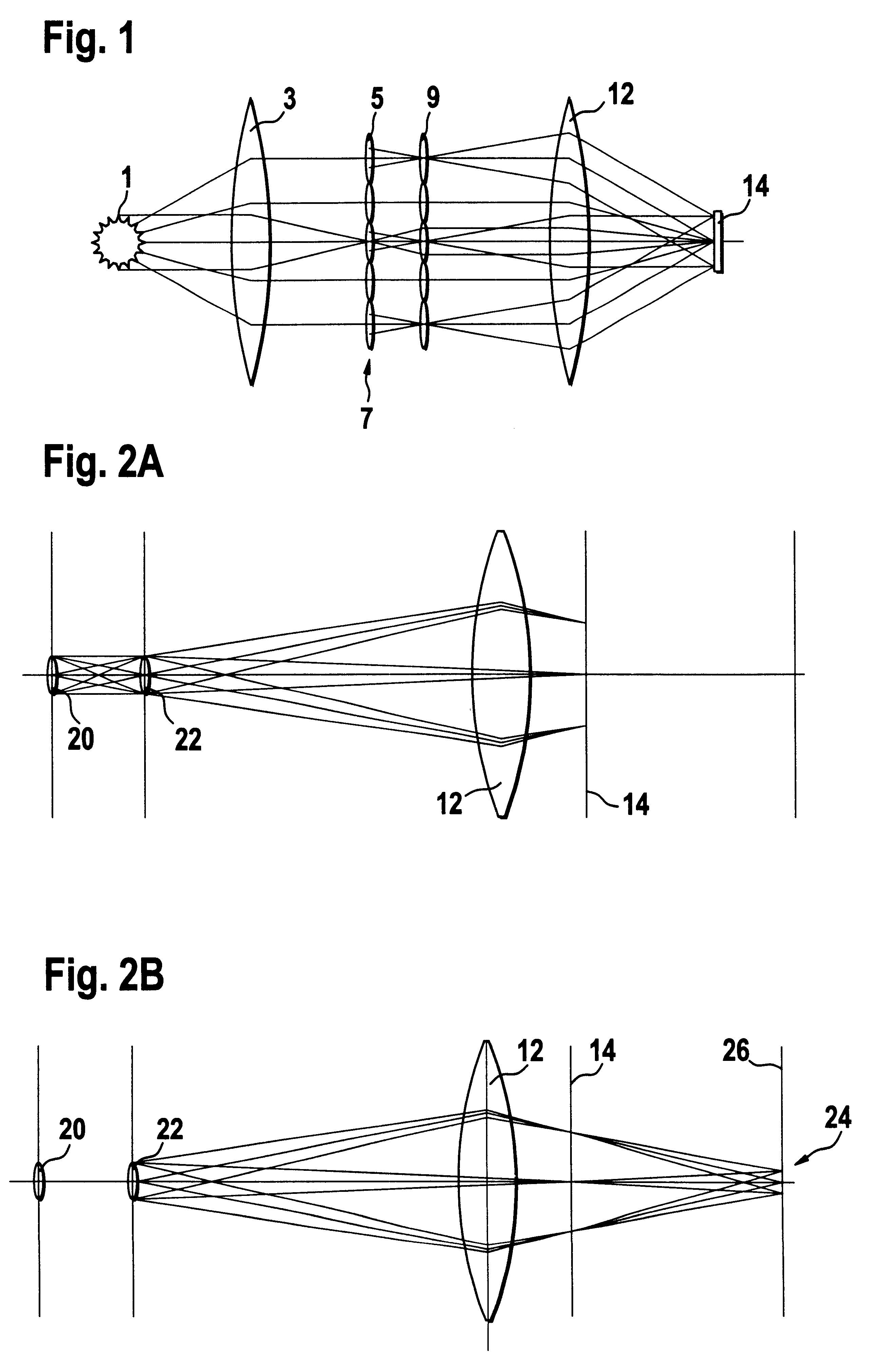
In FIG. 1, a principle diagram of the beam path of a system with two plates with raster elements is illustrated. The light of the primary light source 1 is collected by means of a collector lens 3 and converted into a parallel or convergent light beam. The field raster elements 5 of the first raster element plate 7 decompose the light beam and produce secondary light sources at the site of the pupil raster elements 9. At the position of the secondary light sources the pupil plane of the illumination system is arranged. The field lens 12 images these secondary sources in the exit pupil of the illumination system or the entrance pupil of the subsequent projection objective forming tertiary light sources. The field raster elements 5 are imaged by the pupil raster el...


PUM


Abstract

The invention concerns an illumination system, particularly for microlithography with wavelengths <=193 nm, comprising a light source, a first optical component, a second optical component, an image plane and an exit pupil. The first optical component transforms the light source into a plurality of secondary light sources being imaged by the second optical component in said exit pupil. The first optical component comprises a first optical element having a plurality of first raster elements, which are imaged into said image plane producing a plurality of images being superimposed at least partially on a field in said image plane. The first raster elements deflect incoming ray bundles with first deflection angles, wherein at least two of the first deflection angles are different. The first raster elements are preferably rectangular, wherein the field is a segment of an annulus. To transform the rectangular images of the first raster elements into the segment of the annulus, the second optical component comprises a first field mirror for shaping the field to the segment of the annulus.

Description

1. Field of the InventionThe invention concerns an illumination system for wavelengths .ltoreq.193 nm as well as a projection exposure apparatus with such an illumination system.In order to be able to further reduce the structural widths of electronic components, particularly in the submicron range, it is necessary to reduce the wavelengths of the light utilized for microlithography. Lithography with very deep UV radiation, so called VUV (Very deep UV) lithography or with soft x-ray radiation, so-called EUV (extreme UV) lithography, is conceivable at wavelengths smaller than 193 nm, for example.2. Description of the Prior ArtAn illumination system for a lithographic device, which uses EUV radiation, has been made known from U.S. Pat. No. 5,339,346. For uniform illumination in the reticle plane and filling of the pupil, U.S. Pat. No. 5,339,346 proposes a condenser, which is constructed as a collector lens and comprises at least 4 pairs of mirror facets, which are arranged symmetrical...

Claims


Application Information

Patent Timeline
IPC IPC(8): G03F7/20G21K1/00G21K5/00G21K1/06F21V5/00F21V7/00F21V13/04G02B13/18G02B17/00G02B17/08G02B19/00G21K5/02G21K5/04H01L21/027
CPCB82Y10/00G03F7/70075G03F7/70083G03F7/70091G03F7/70108G03F7/70166G03F7/702G03F7/70233G03F7/70358G03F7/708G03F7/70891G21K1/06G21K1/067G21K2201/06G21K2201/064G03F7/20
Inventor SCHULTZ, JORGWANGLER, JOHANNESSCHUSTER, KARL-HEINZDINGER, UDOSINGER, WOLFGANGANTONI, MARTIN
Owner CARL-ZEISS-STIFTUNG TRADING AS CARL ZEISS
Why Eureka
Try Eureka