Eureka AIR delivers breakthrough ideas for toughest innovation challenges, trusted by R&D personnel around the world.

Holographic recording method, holographic recording apparatus, holographic memory reproducing method, holographic memory reproducing apparatus, holographic recording and reproducing apparatus, and holographic recording medium

a recording method and recording technology, applied in the field of recording information, can solve the problems of reducing the recording rate and the contrast of interference fringes, increasing the volume of the apparatus, and increasing the utilization efficiency of the reference beam, so as to increase the angle modulation spacing of the reference beam and reduce the beam diameter

Inactive Publication Date: 2009-05-12
TDK CORPARATION
View PDF5 Cites 2 Cited by
  • Summary
  • Abstract
  • Description
  • Claims
  • Application Information

AI Technical Summary

Benefits of technology

[0009]This invention has been made in view of the abovementioned problems. Accordingly, it is an object of the invention to provide a holographic recording method, a holographic recording apparatus, a holographic memory reproducing method, a holographic memory reproducing apparatus, a holographic recording and reproducing apparatus, and a holographic recording medium, in each of which the distance between an address detector and a holographic recording medium can be reduced without decreasing the beam diameter of an object beam and increasing the angle modulation spacing of a reference beam.
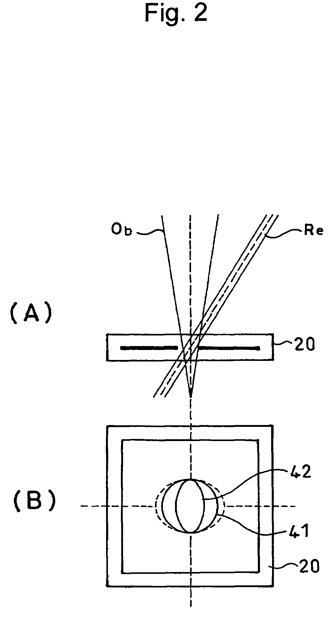
[0010]The present inventor has conducted intensive studies and has consequently found that, by transforming the shape of a reference beam into an elongated shape having a minor axis coincident with an angle modulation direction, the distance of an address detector with respect to a holographic recording medium can be shortened without reducing the beam diameter of the object beam and the maximum beam diameter of the reference beam and without increasing an angle modulation spacing.

Problems solved by technology

Thus, a problem arises that the volume of an apparatus increases.
Moreover, if the beam diameters of the reference beam and the object beam are reduced, the utilization efficiency of the reference beam is lowered, causing new problems that a recording rate and the contrast of interference fringes are lowered.

Method used


Image

  • Holographic recording method, holographic recording apparatus, holographic memory reproducing method, holographic memory reproducing apparatus, holographic recording and reproducing apparatus, and holographic recording medium
  • Holographic recording method, holographic recording apparatus, holographic memory reproducing method, holographic memory reproducing apparatus, holographic recording and reproducing apparatus, and holographic recording medium
  • Holographic recording method, holographic recording apparatus, holographic memory reproducing method, holographic memory reproducing apparatus, holographic recording and reproducing apparatus, and holographic recording medium

Examples


first embodiment

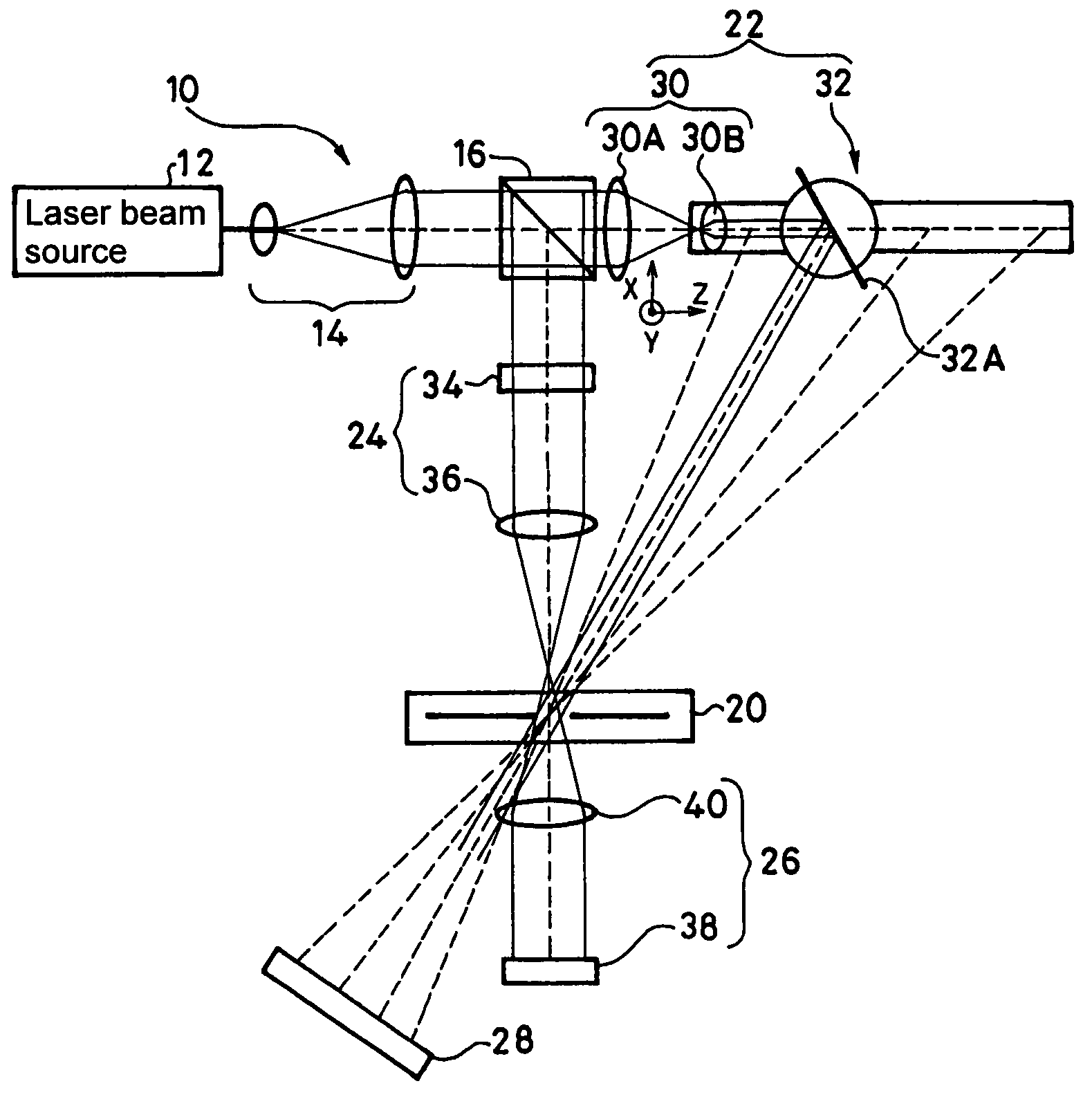
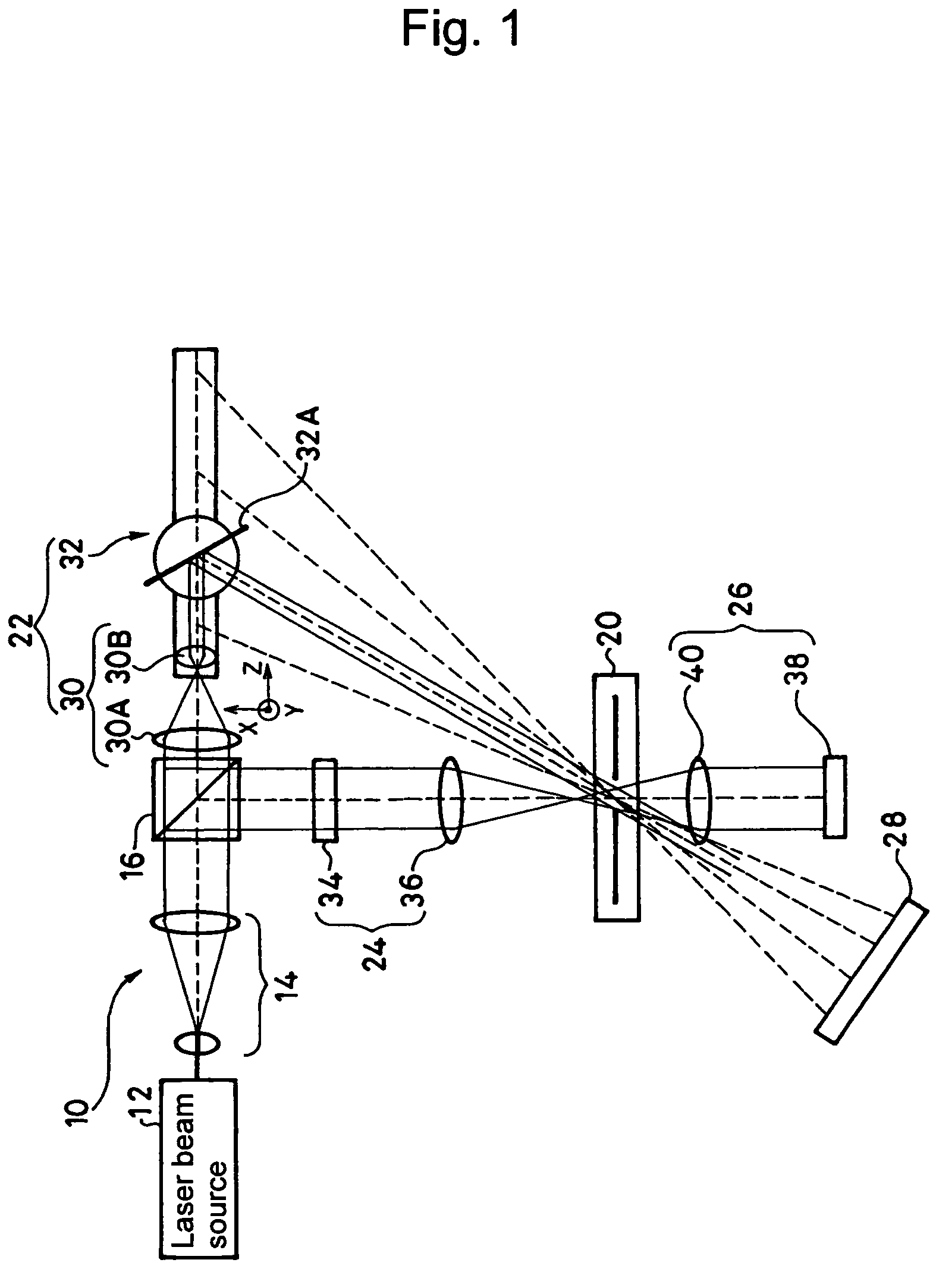
[0038]A first embodiment of the present invention will next be described with reference to FIGS. 1 and 2.

[0039]As shown in FIG. 1, a holographic recording and reproducing apparatus 10 according to the first embodiment includes: a laser beam source 12; a beam expander 14 for expanding the beam diameter of the laser beam emitted from this laser beam source 12; a beam splitter 16 which splits this laser beam having the beam diameter expanded by this beam expander 14 into a transmission beam and a reflection beam; a reference optical system 22 for guiding the transmission beam from the beam splitter 16 to a holographic recording medium 20 as a reference beam; an object optical system 24 for guiding the reflection beam to the abovementioned holographic recording medium 20 as an object beam; an imaging optical system 26 which is arranged on a line extending the optical axis of the abovementioned object beam having passed through the holographic recording medium 20; and an address detector...

second embodiment

[0070]A second embodiment shown in FIG. 7 is a reproducing-specific apparatus for reproducing information recorded on the holographic recording medium 20 in which angle multiplex recording is performed by use of the reference beam having the elongated beam shape by means of the abovementioned holographic recording and reproducing apparatus 10 or the like.

[0071]This holographic memory reproducing apparatus 50 is configured to include: a data search optical system 52 which is employed only for data search; a reproduction beam source 54 for forming a reproduction beam; and an imaging optical system 56 for reproducing information from a diffraction beam generated by projecting the reproduction beam from the reproduction beam source 54 onto the holographic recording medium 20.

[0072]The abovementioned data search optical system 52 is configured to include: a laser beam source 52A; a search-specific spatial light modulator 52B for providing a laser beam emitted from the laser beam source 5...


PUM

PropertyMeasurementUnit
incident angleaaaaaaaaaa
diameteraaaaaaaaaa
diameteraaaaaaaaaa

Abstract

The pitch of light beam spots on a light receiving surface of an address detector upon search of information recorded on a holographic recording medium is decreased to reduce a distance between the holographic recording medium and the address detector. In a holographic recording and reproducing apparatus 10, a reference beam having an elliptical beam shape transformed by a beam shaping optical system 30 and an object beam having an unchanged circular shape are projected onto a holographic recording medium 20 so that interference fringes are allowed to be formed only within the elliptical shape. Therefore, even when the distance of an address detector 28 from the holographic recording medium 20 is reduced, crosstalk is prevented between array-shaped two-dimensional photodetectors 28A, 28B, 28C, and so on constituting the address detector 28.

Description

TECHNICAL FIELD[0001]This invention relates to a holographic recording method for recording information by forming interference fringes of an object beam and a reference beam on a holographic recording medium, a holographic recording apparatus for recording information, a holographic memory reproducing method and apparatus for reproducing holographic-recorded information, a holographic recording and reproducing apparatus for holographic recording-reproducing, and a holographic recording medium in which information is formed by means of interference fringes.BACKGROUND ART[0002]As one of the conventional holographic recording methods of this type, an angle multiplex holographic recording method is known in which the incident angle of a reference beam with respect to a holographic recording medium is modulated while an object beam is fixed. In this case, the beam shapes of the object beam and the reference beam are both circular.[0003]In a holographic recording medium in which angle mu...

Claims


Application Information

Patent Timeline
Patent Type & Authority Patents(United States)
IPC IPC(8): G03H1/28G11B7/00G03H1/04G03H1/22G03H1/26G11B7/0065G11B7/085G11B7/135G11B7/1398
CPCG03H1/04G03H1/0465G03H1/26G03H1/265G11B7/0065G11B7/08505G11B7/1398
Inventor TSUKAGOSHI, TAKUYAYOSHINARI, JIROMIURA, HIDEAKIMIZUSHIMA, TETSURO
Owner TDK CORPARATION
Why Eureka
Eureka Blog
Learn More