Optical scanner and light source module

A technology of optical scanners and light sources, applied in the field of optical scanners, can solve the problems of equal distance, obstruction of the first focus and second focus, deviation, etc.

Inactive Publication Date: 2004-08-18
FUJITSU LTD
View PDF0 Cites 0 Cited by
  • Summary
  • Abstract
  • Description
  • Claims
  • Application Information

AI Technical Summary

Problems solved by technology

[0007] However, due to the complexity of the optics in prior art optical scanners, it is difficult to make these two distances equal to the light source, with the result that the focal point of the first beam component X may be arranged in the center of the optimum readout zone , while the focus of the second beam component Y deviates from the center of the optimum readout area
In this case, the barcode cannot be read using the second scanning light
Therefore, achieving optimal first and second focus is prevented, and when the two laser beam components pass through the "optimal read zone", one of them cannot read or scan the barcode

Method used


Image

  • Optical scanner and light source module
  • Optical scanner and light source module
  • Optical scanner and light source module

Examples


Embodiment Construction

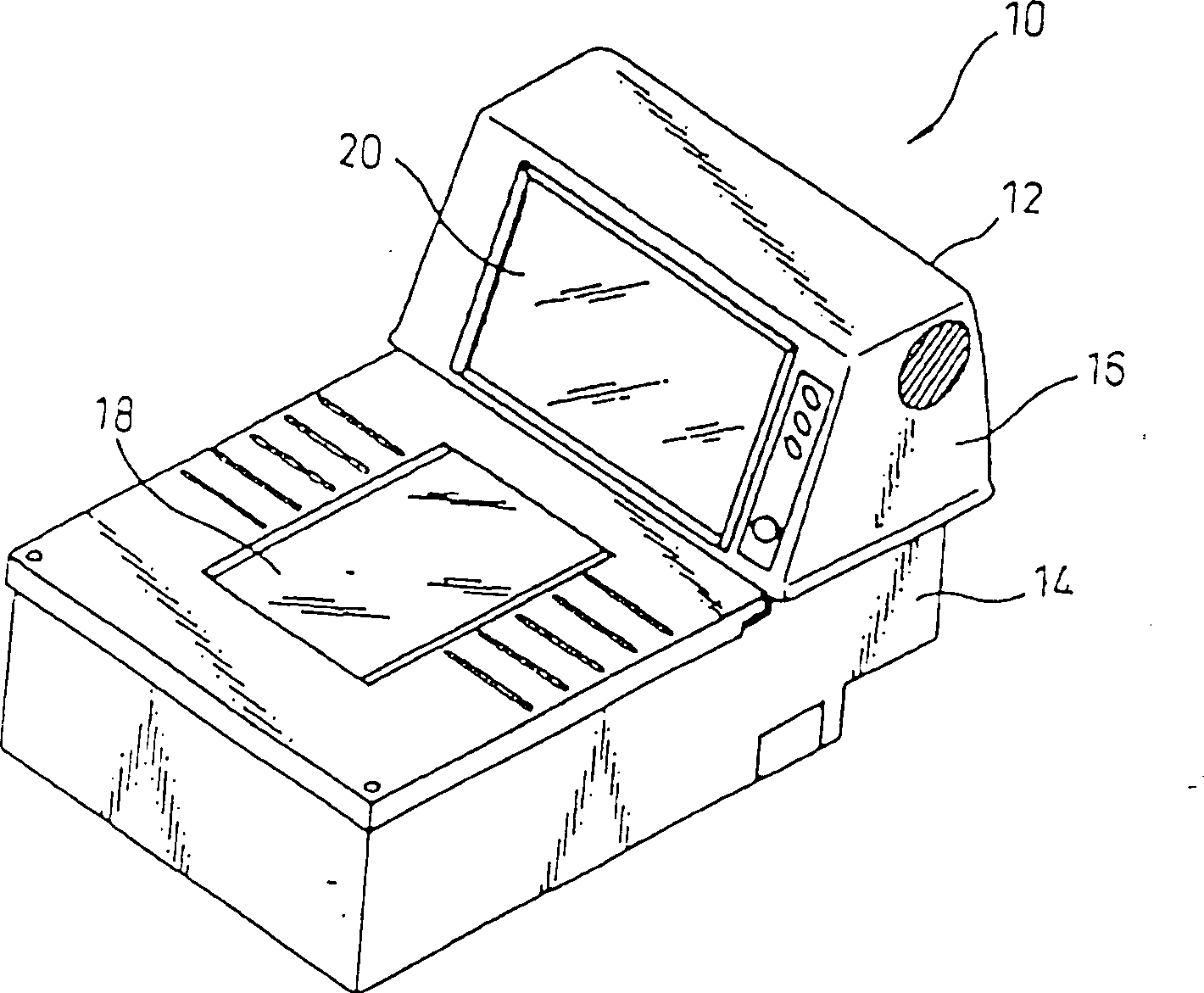
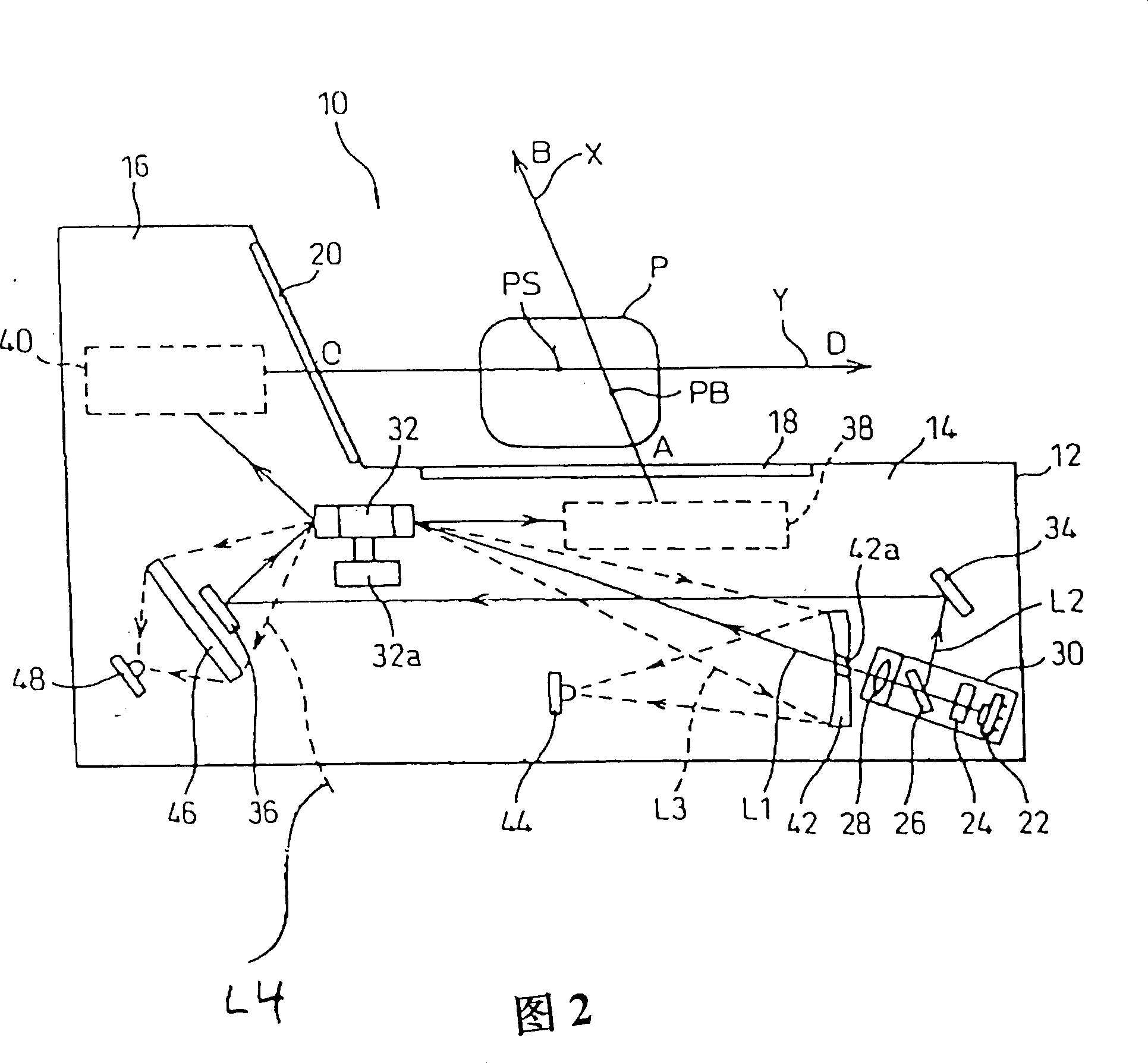
[0051] figure 1 and FIG. 2 shows an exemplary diagram of an optical scanner, such as a bar code reader, in accordance with one embodiment of the present invention. The optical scanner 10 includes a body 12 , a base 14 and a top cover portion 16 .

[0052] The bottom readout window 18 is on the surface of the bottom portion 14 and the side readout window 20 is on the surface of the top cover portion 16 . The bottom readout window 18 and the side readout window 20 are placed at an included angle, roughly in an "L" shape.

[0053] As shown in FIG. 2, the light beam emitted from the bottom readout window 18 is indicated by an arrow X, and the other beam emitted from the side readout window 20 is indicated by an arrow Y. The optimum readout area (area P) is above the bottom readout window 18 , and the center of the optimum readout area is a predetermined distance from the side readout window 20 . Therefore, when the object is in the optimum reading area (area P), it is possible ...


PUM


Abstract

A point of sale (POS) device, such as an optical scanner, the beam diameters of two light beam components having been emitted from a common light source and split by an optical beam splitter may be reduced, which includes a light source for emitting a light beam, a light beam splitter for splitting the emitted light beam, a polygon mirror for reflecting the split light beam components into mutually different directions, and groups of mirrors. The groups of mirrors are provided for each reading window, allowing the light beam components to be emitted therefrom. The emitted light beam components can then incidence on an object, whereupon the optical scanner detects by detectors and reads a bar code located on the object.

Description

technical field [0001] The present invention relates generally to optical scanners, and more particularly, the present invention relates to methods and apparatus for reducing the beam diameters of two separate beam components emanating from the same light source for use in optical scanners. Background technique [0002] Point-of-sale (POS) systems, such as optical scanners, which detect and read light reflected from barcodes attached to merchandise, are widely used. For example, optical scanners, also known as barcode readers, are used at "cash" counters in grocery stores to scan barcodes attached to merchandise such as food. By moving and manipulating merchandise, these optical scanners help operators, such as cashiers, reduce the time required to "scan" information about merchandise, thereby reducing operator burden and increasing operator productivity. [0003] In recent years, optical scanners have been developed with two readout windows, for example, arranged at the bo...

Claims


Application Information

Patent Timeline
Patent Type & Authority Patents(China)
IPC IPC(8): G06K7/10
CPCG06K7/1096G06K7/10693G06K7/10
Inventor 大川正德市川稔幸绵贯洋山崎行造
Owner FUJITSU LTD
Why Eureka
Try Eureka