
Process for producing dimethyl sulfoxide

a technology of dimethyl sulfoxide and dimethyl sulfoxide, which is applied in the direction of physical/chemical process catalysts, organic chemistry, chemistry apparatus and processes, etc., can solve the undesirable dispersal of used catalyst nox, high cost and effective utilization of resources, and high purchase price of highly pure oxygen gas with an oxygen concentration of 99% or more used here, so as to improve the recovery rate and/or absorption rate of nox, the effect of efficient dms

Inactive Publication Date: 2002-07-02
TORAY FINE CHEMICALS CO LTD
View PDF10 Cites 4 Cited by
  • Summary
  • Abstract
  • Description
  • Claims
  • Application Information

AI Technical Summary

Benefits of technology

An object of the present invention is to provide an efficient DMSO production process improved in the conversion from DMS to DMSO in the continuous oxidation reaction of DMS for producing DMSO by recycling NOx used as a catalyst, in order to improve the disadvantage of having to dispose of the used catalyst in the prior art. More specifically, it is an object to provide a DMSO production process improved in the recovery rate and / or absorption rate of NOx by recovering NOx from the reaction off gas and / or the gas removed from the reaction product solution, in the reaction to continuously oxidize DMS by a gas mainly composed of oxygen, using NOx as a catalyst in a liquid phase for producing DMSO.
Another object of the present invention is to provide a low-cost DMSO production process allowing the use of simpler production equipment, by using relatively low pure oxygen gas obtained by the pressure swing adsorption treatment of air.
The inventors studied intensively to solve the above problems and, as a result, found that dimethyl sulfoxide (DMSO) can be produced very efficiently at a high yield, by supplying at least partially the reaction product solution containing dimethyl sulfoxide (DMSO) and NOx obtained by oxidation reaction of dimethyl sulfide (DMS) to said oxidation reaction for recycling.

Problems solved by technology

So, since the conventional process requires a considerable amount of catalyst NOx, the disposal of used catalyst NOx is undesirable in view of cost and effective utilization of a resource.
However, the highly pure oxygen gas with an oxygen concentration of 99% or more used here is high in purchase price, and requires large equipment such as a receiving tank for use of oxygen.

Method used


Image

  • Process for producing dimethyl sulfoxide
  • Process for producing dimethyl sulfoxide

Examples


example 1

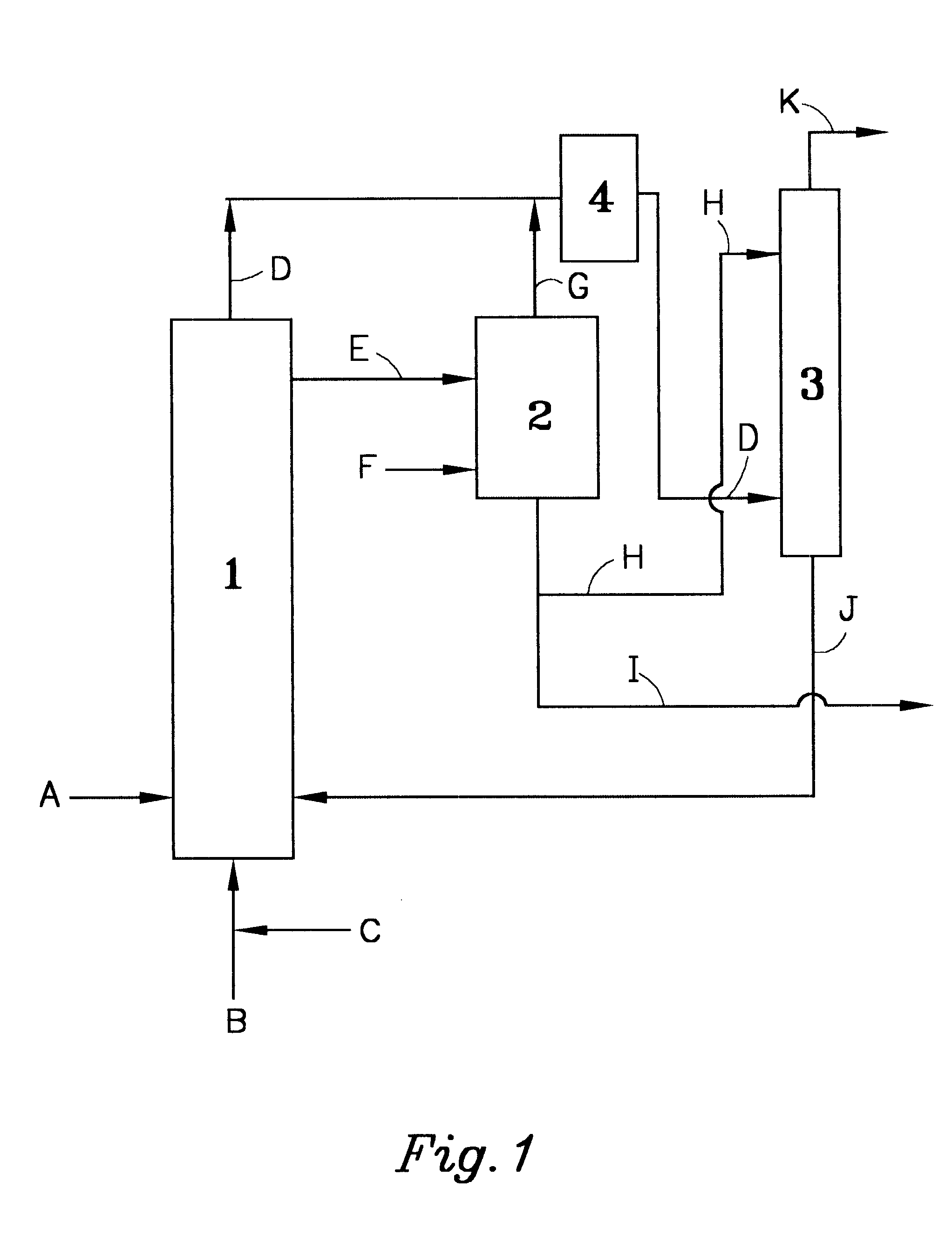
The drawing illustrates the outline of the recovery equipment and process used for recovering NOx of the present invention.

In the drawing, DMS was supplied from a pipe 1 at a rate of 100 g per hour (hereinafter expressed as (g / h)), catalyst NOx, from a pipe 2 at a rate of 0.6 (g / h), and oxygen, from a pipe 3 at a rate of 30.5 (g / h), respectively, to an oxidation reactor 4 (4 cm dia. .times.50 cm), and oxidation reaction was effected at a reactor temperature of 30.degree. C. The reaction off gas containing oxygen and NOx was supplied through a pipe 5 to a NO oxidizing reactor 6 and a NOx absorbing column 7 (1 cm dia..times.50 cm) for recovery of NOx. To a degassing tank 8 (2 cm dia..times.20 cm), the reaction product solution produced in the oxidation reactor 4 was supplied from a pipe 9, and furthermore nitrogen gas was supplied from a pipe 10 at a rate of 10 (g / h), to remove NOx in the reaction product solution. The temperature of the degassing tank 8 was 50.degree. C. The NOx remo...

example 2

In the drawing, DMS was supplied from the pipe 1 at a rate of 100 (g / h), catalyst NOx, from the pipe 2 at a rate of 6.2 (g / h) and a gas with an oxygen concentration of 90% obtained by PSA, from the pipe 3 at a rate of 34.0 (g / h), respectively to the oxidation reactor 4, and oxidation reaction was effected at a reactor temperature of 30.degree. C. The reaction product solution mainly composed of DMSO produced in the oxidation reactor 1 was supplied from the pipe 9 to the subsequent step. The amount of the reaction product solution supplied in this case was 124.8 (g / h) . Furthermore, the reaction off gas containing oxygen and NOx was supplied from the pipe 5 to the subsequent step. The amounts of oxygen and NOx in the reaction off gas in this case were 12.2 (g / h) and 2.4 (g / h) respectively. The conversion into DMSO in this DMS liquid phase continuous oxidation was more than 99%.

example 3

In the drawing, DMS was supplied from the pipe 1 at a rate of 100 (g / h), catalyst NOx, from the pipe 2 at a rate of 0.6 (g / h) and a gas with an oxygen concentration of 90% obtained by PSA, from the pipe 3 at a rate of 34.0 (g / h), respectively to the oxidation reactor 4, and oxidation reaction was effected at a reactor temperature of 30.degree. C. The reaction off gas containing oxygen and NOx was supplied through the pipe 5 to the NO oxidizing reactor 6 and the NOx absorbing column 7 for recovery of NOx. The reaction product solution produced in the oxidation reactor 4 was supplied from the pipe 9 to the degassing tank 8 at a rate of 124.5 (g / h), and furthermore nitrogen gas was supplied to the degassing tank 2 from the pipe F at a rate of 10 (g / h) , to remove NOx in the reaction product solution. The temperature of the degassing tank 2 in this case was 50.degree. C. The removed NOx was supplied to the NO oxidizing reactor 6 and the NOx absorbing column 7 through the pipes 11 and 5....


PUM

PropertyMeasurementUnit
Angleaaaaaaaaaa
Angleaaaaaaaaaa
Angleaaaaaaaaaa

Abstract

The present invention provides an efficient dimethyl sulfoxide (DMSO) production process improved in the conversion from dimethyl sulfide (DMS) to DMSO by recycling the NOx used as a catalyst in the continuous oxidation reaction of DMS for producing DMSO, specifically providing a DMSO production process improved in the recovery rate and / or absorption rate of NOx by recovering NOx from the reaction off gas and / or the gas removed from the reaction product solution for re-utilization.

Description

The present invention relates to a process for producing dimethyl sulfoxide (hereinafter called DMSO) industrially widely used, for example, as a reaction solvent of medical and agricultural intermediate products, a synthetic reagent or as a special detergent for electronic materials, and the like. In more detail, the present invention relates to an improvement for the process of continuously oxidizing dimethyl sulfide (hereinafter called DMS) using NOx (a mixture of NO, N.sub.2 O.sub.3, NO.sub.2 or N.sub.2 O.sub.4 or mixture thereof) as a catalyst in a liquid phase for producing DMSO.PRIOR ARTAs a conventional process for producing DMSO, a process of continuously oxidizing DMS using NOx as a catalyst in a liquid phase is publicly known (U.S. Pat. No. 2,825,744 and Japanese Patent Publication (Kokoku) No. Sho 42-9771).In the DMS oxidizing reaction, NOx gas to be used as a catalyst is supplied together with a gas mainly composed of oxygen to be used as an oxidizing agent to a DMS-con...

Claims


Application Information

Patent Timeline
IPC IPC(8): C07C315/00C07C315/02C07C317/04C07C317/00B01J27/24C07B61/00
CPCC07C315/02C07C317/04Y02P20/584
Inventor FUKUI, YOSHIYUKIABURAI, KOUJISAKAMOTO, KOSUKE
Owner TORAY FINE CHEMICALS CO LTD
Learn More