
Electrochemical cell

a technology of electrochemical cells and electrodes, applied in the field of electrochemical cells, can solve the problems of inability to achieve the objectives of sensors intended, and interference in the determination, so as to improve accuracy, reliability and/or speed.

Inactive Publication Date: 2002-07-02
LIFESCAN INC
View PDF109 Cites 486 Cited by
  • Summary
  • Abstract
  • Description
  • Claims
  • Application Information

AI Technical Summary

Benefits of technology

It is an object invention to provide a method of analysis and apparatus fore method which avoid or ameliorate at least some of the disadvantages of the prior art It is an object of preferred forms of the invention to provide a biosensor of improved accuracy, and / or reliability and / or speed and a method for its use.
The concentration measured in this way is substantially independent of variation if any in the diffusion coefficient of the reduced form, and therefore is compensated for variations in temperature and viscosity. The concentration so measured is independent of variations in haematocrit and other substances which affect the diffusion coefficient of the reduced form of the redox species.
This allows a steady state concentration profile to be achieved between the electrodes leading to a steady state current. This in turn allows the diffusion coefficient and concentration of the redox species (mediator) to be measured independently of sample variations and therefore greatly improves accuracy and reliability.
It is thus possible to fill a thin layer electrochemical cell with plasma substantially free of hematocrit which would cause a variation in the diffusion coefficient of the redox mediator and which would affect the accuracy of the test as hereinafter explained.

Problems solved by technology

Each batch of cells is required to have been previously calibrated and leads to inaccuracies during use because of variations within the batch, in sample composition, and in ambient conditions.
Achievement of these objectives is made difficult in the case of sensors intended to determine the concentration of analytes in blood because blood contains dissolved gases, ions, colloids, complex micelles, small scale cellular debris, and living cellular components in a predominantly aqueous medium.
Any of these may interfere in the determination.
Existing sensors are also susceptible to influence from other interfering substances that may present in the sample and which may be oxidised at the working electrode and mistakenly identified as the analyte of interest.
Thus high oxygen concentrations can lead to low estimates of glucose concentration.

Method used


Image

  • Electrochemical cell
  • Electrochemical cell
  • Electrochemical cell

Examples


first embodiment

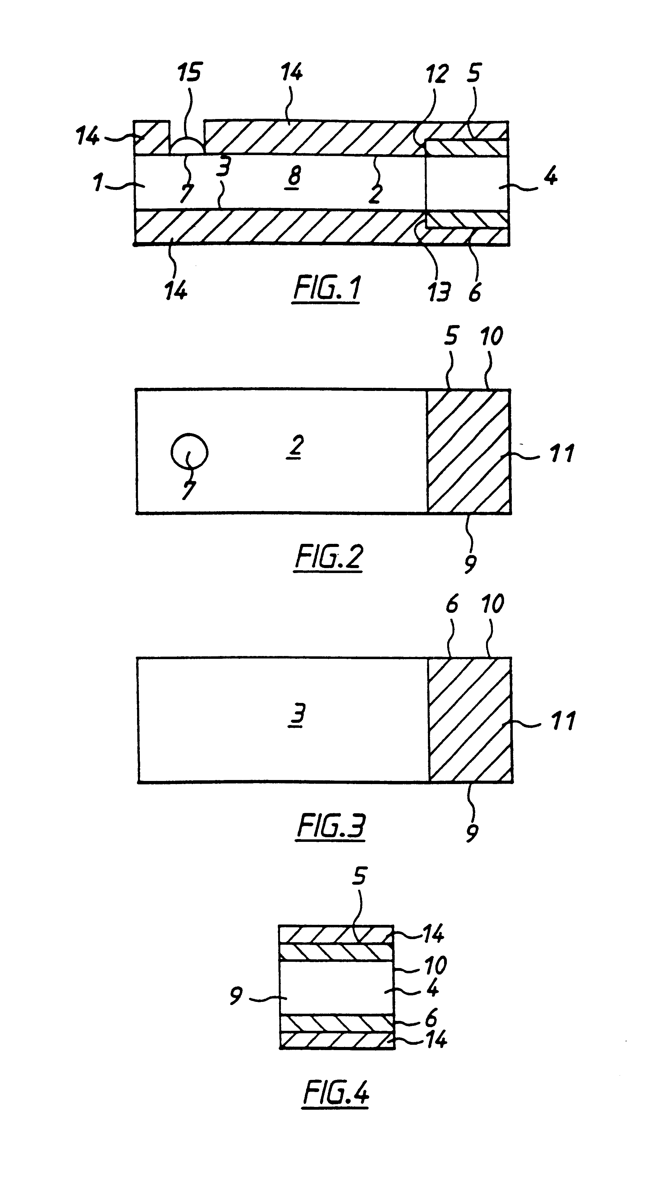
With reference to FIGS. 1 to 4 there is shown apparatus of the invention, in this case a biosensor for determining glucose in blood. The embodiment comprises a thin strip membrane 1 having upper and lower surfaces 2, 3 and having a cell zone 4 defined between a working electrode 5 disposed on upper surface 2 and a counter electrode 6 disposed on lower surface 3. The membrane thickness is selected so that the electrodes are separated by a distance "l" which is sufficiently close that the products of electrochemical reaction at the counter electrode migrate to the working electrode during the time of the test and a steady state diffusion profile is substantially achieved. Typically, "l" will be less than 500 .mu.m. A sample deposition or "target" area 7 defined on upper surface 2 of membrane 1 is spaced at a distance greater than the membrane thickness from cell zone 4. Membrane 1 has a diffusion zone 8 extending between target area 7 and cell zone 4. A suitable reagent including a re...

second embodiment

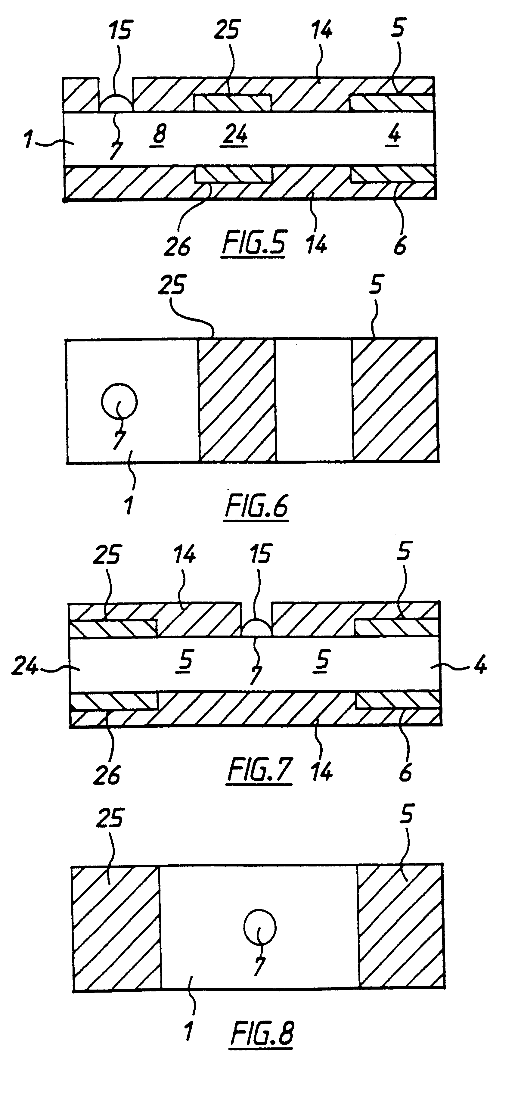
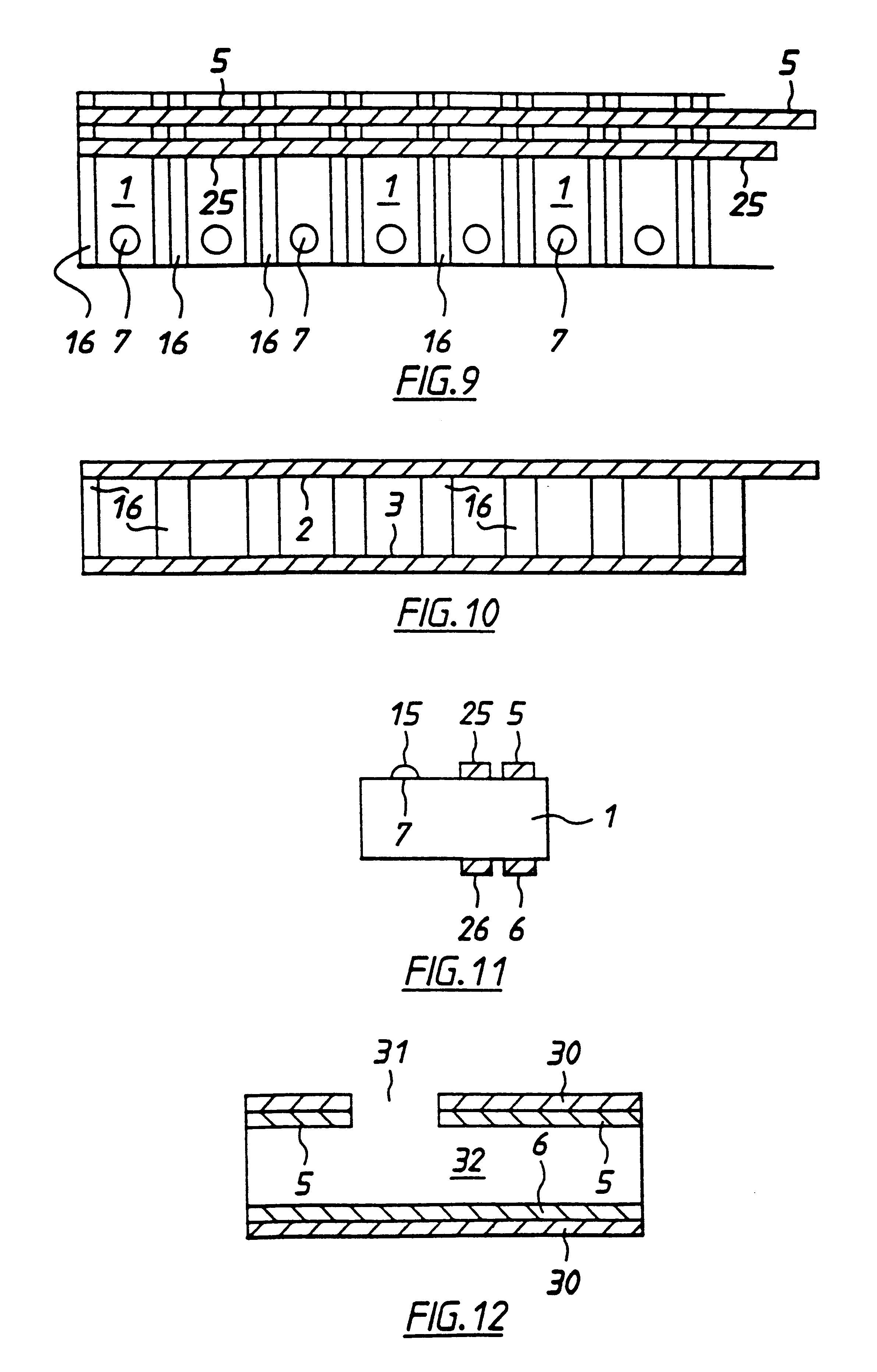
A second embodiment according to the invention, shown in FIGS. 5 and 6, differs from the first embodiment by inclusion of a second working electrode 25 and counter / reference electrode 26 defining a second cell zone 24 therebetween. These electrodes are also spaced apart by less than 500 .mu.m in the present example. Second electrodes 25, 26 are situated intermediate cell zone 4 and target area 7. In this embodiment the redox mediator is contained in the membrane below or adjacent to target area 7 or intermediate target area 7 and first cell zone 4. The enzyme is contained in the membrane in the first cell zone 4 and second cell zone 24. The enzyme does not extend into second cell 24. In this case when blood is added to the target area, it dissolves the redox mediator. This wicks along the membrane so that second electrochemical cell 24 contains redox mediator analyte and serum including electrochemically interfering substances. First electrochemical cell receives mediator, analyte, ...

example 1

A membrane 130 microns thick was coated on both sides with a layer of Platinum 60 nanometers thick. An area of 12.6 sq. mm was defined by compressing the membrane. 1.5 microliters of a solution containing 0.2 Molar potassium ferricyanide and 1% by weight glucose oxidase dehydrogenase was added to the defined area of the membrane and the water allowed to evaporate.

The platinum layers were then connected to a potentiostat to be used as the working and counter / reference electrodes. 3.0 microliters of an aqueous solution containing 5 milimolar D-glucose and 0.9 wt % NaCl was dropped on to the defined area of the membrane. After an elapse of 20 seconds a voltage of 300 millivolts was applied between the working counter / reference electrodes and the current recorded for a further 30 seconds at intervals of 0.1 seconds.

FIG. 13 is a graph of current versus time based on the above measurements. Using a value of the steady state current of 26.9 microamps the function ln(i / 26.9-1) was computed ...


PUM

PropertyMeasurementUnit
Distanceaaaaaaaaaa
Distanceaaaaaaaaaa
Distanceaaaaaaaaaa

Abstract

This invention relates to a biosensor and more particularly to an electrochemical biosensor for determining the concentration of an analyte in a carrier. The invention is particularly useful for determining the concentration of glucose in blood and is described herein with reference to that use but it should be understood that the invention is applicable to other analytic determinations.

Description

This invention relates to a biosensor and more particularly to an electrochemical biosensor for determining the concentration of an analyte in a carrier. The invention is particularly useful for determining the concentration of glucose in blood and is described herein with reference to that use but it should be understood that the invention is applicable to other analytic determinations.Electrochemical biosensors generally comprise a cell having a working electrode, a counter electrode and a reference electrode. Sometimes the function of the counter and reference electrodes are combined in a single electrode called a "counter / reference" electrode or "pseudo reference electrode". As herein used the term "counter electrode" includes a counter / reference electrode where the context so admits.The sample containing the analyte is brought into contact with a reagent containing an enzyme and a redox mediator in the cell. Either the mediator is reduced (receives at least one electron) while ...

Claims


Application Information

Patent Timeline
IPC IPC(8): G01N27/49C12Q1/00G01N27/327
CPCC12Q1/004G01N27/3273G01N27/403G01N27/3272Y10T29/49117
Inventor HODGES, ALASTAIR MCINDOEBECK, THOMAS WILLIAMJOHANSEN, ODDVAR
Owner LIFESCAN INC
Learn More