
Biological sensor

Inactive Publication Date: 2002-06-25
NIHON KOHDEN CORP
View PDF11 Cites 37 Cited by
  • Summary
  • Abstract
  • Description
  • Claims
  • Application Information

AI Technical Summary

Benefits of technology

The invention has been devised in view of the above-described circumstances, and its object is to provide a biological sensor capable of stably measuring a gas or ion concentration in living tissues without damaging the living tissues. Another object of the invention is to provide a biological sensor which can be easily secured at a measurement region of an object.
In biological sensor according to the first and second aspects of the present invention, since the sensor sensitive portion for detecting the concentration of a gas or ions from living tissues is surrounded by the protecting portion having a thickness larger than the thickness of the sensor sensitive portion, by placing the protecting portion between the living tissues, a signal representing the concentration of a gas or the like in the living tissues can be outputted stably without causing the living tissues to come into direct contact with the sensitive portion.
In biological sensor according to fourth to seventh aspects, since the metallic protecting portion and the metal member are electrically grounded, it is possible to reduce induction noise due to high frequencies from an electric cautery or the like to which the leading portion is subjected, thereby making it possible to obtain a stable signal output. Namely, since the induction noise caused by electric cautery is likely to affect the sensor signal through the leading portion, the grounding of the metal member of the plasticity material produces a large effect. In cases where the plasticity material does not include a metal member, it is possible to enhance the effect by leading the grounding line of the protecting portion together with the tube. Further, in order to obtain an enhanced effect, it is preferable to include a metal member in the plasticity material and ground both the metallic protecting portion and the plasticity material.
In biological sensor according to the eighth aspect of the present invention, by covering the metal wire having plasticity with the flexible synthetic resin tube, it is possible to prevent the danger of elution of metal ions and leakage current into the living tissue and the like.
In biological sensor according to a ninth aspect of the present invention, the protecting portion prevents an excess pressure from being applied to the sensor sensitive portion when the biological sensor is disposed in the organism, and the protecting portion causing the gas to diffuse toward the sensor sensitive portion from at least two directions.

Problems solved by technology

However, according to the gas sensor disclosed in Examined Japanese Patent Publication Hei. 4-32985, since porous hollow fiber 8 is likely to be deformed by the external pressure since it has plasticity, and since the gate portion 7 of the ISFET 1 is subjected to pressure from the living tissues through the porous hollow fiber 8, the output of the sensor becomes unstable.
Further, since the ISFET 1 and the reference electrode 2 are formed of rigid materials, if they are subjected to an external force, there are possibilities that these members become broken and that the gas permeable membrane 10 is punctured thereby, causing damage to the sensor structure.
On the other hand, according to the gas sensor disclosed in Unexamined Japanese Sho. 58-97346, since the tube 5 is punctured into the living tissues through the needle 11, there has been a drawback in that the living tissues can be damaged.
In addition, with the above-described two conventional examples, since no consideration is given to the fixation of the sensor to the object, there has been a problem in that the sensor is likely to come off.
Furthermore, since a shielding structure is not provided for protecting from induction noise an unillustrated leading portion for leading a signal detected by the ISFET 1 to the outside, the sensor is susceptible to the effect of such as an electric cautery, so that there has been a problem in that the signal output changes.

Method used


Image

  • Biological sensor
  • Biological sensor
  • Biological sensor

Examples


Embodiment Construction

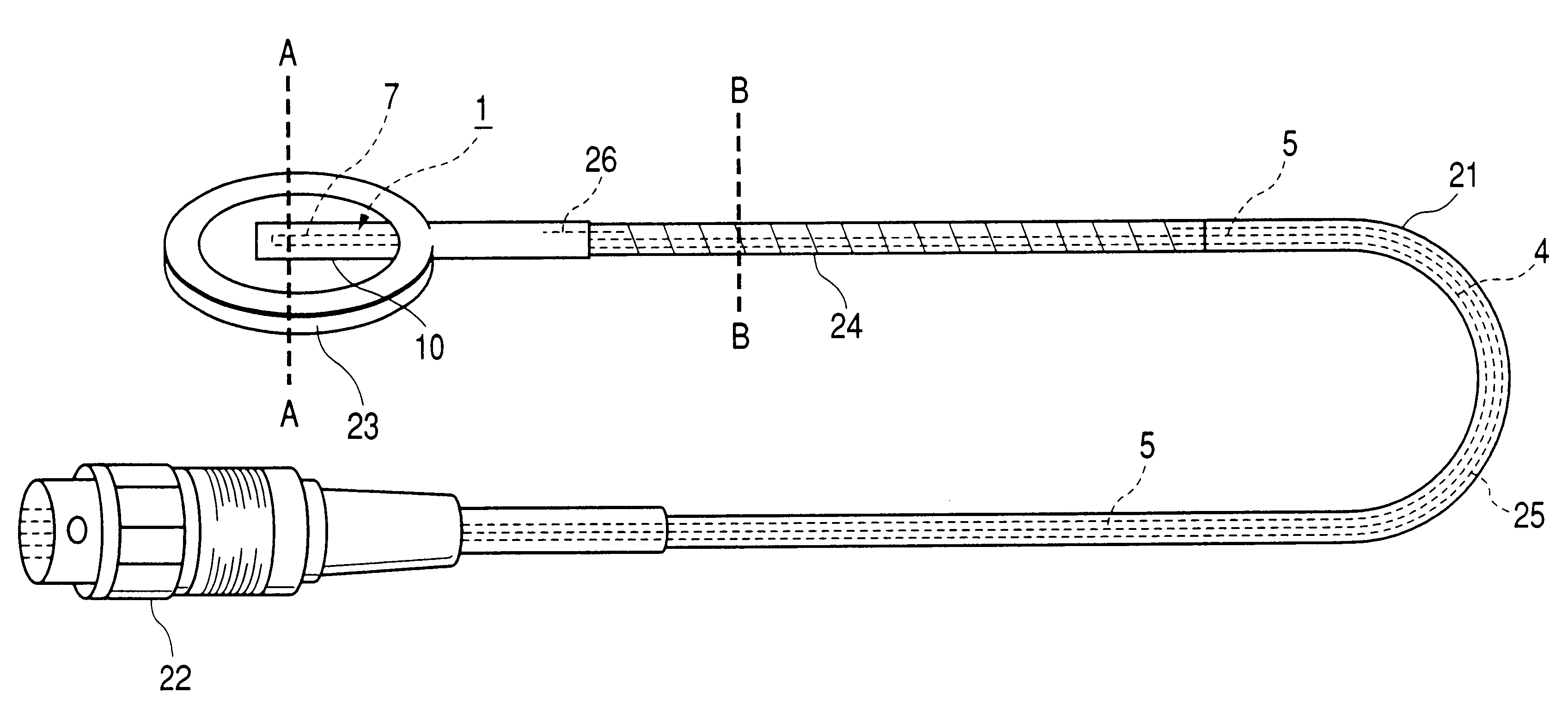
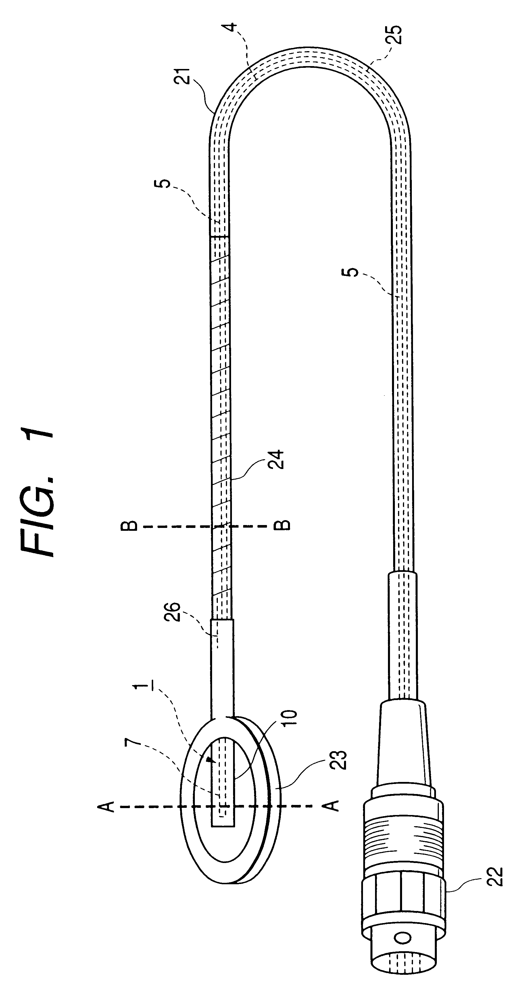
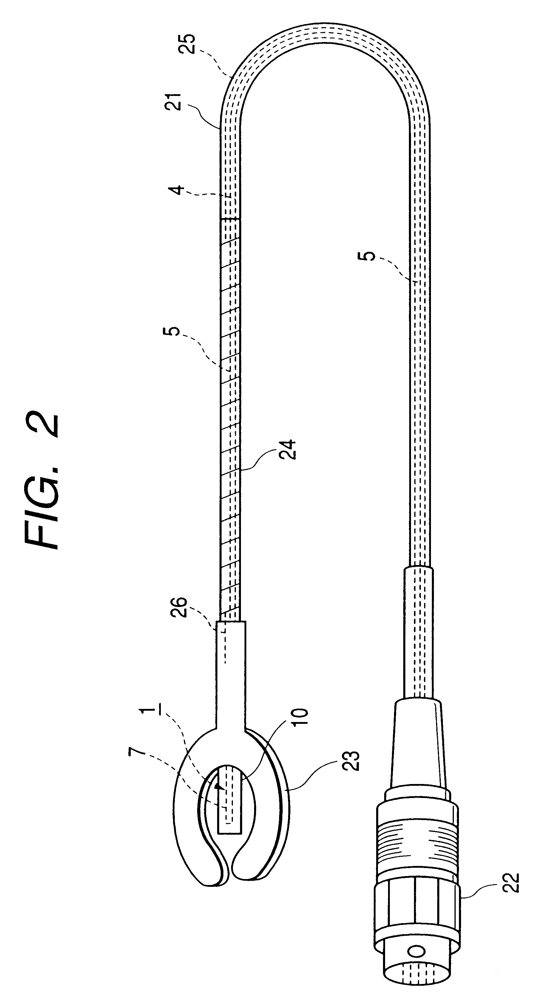
Referring now to the drawings, a description will be given of an example of the construction of an embodiment of a biological sensor in accordance with the invention. FIG. 1 is a perspective view illustrating a first example of the construction in accordance with an embodiment of the invention. In FIG. 1, portions corresponding to the portions of the conventional example are denoted by the same reference numerals, and a description thereof will be omitted, as required.

An ISFET 1 is provided with a reference electrode 2 and electrode portions 3, although not shown, in the same way as the conventional example shown in FIG. 3, and lead wires 4 are connected to the electrode portions 3, respectively. A gate portion 7 at a distal end of the ISFET 1 and a portion of an outer periphery of the reference electrode 2 are covered with a gas-permeable silicone membrane 10. In addition, a tube 5 serving as a leading portion for accommodating the lead wires 4 is covered with a cable cover 21, and...


PUM


Abstract

An annul protecting portion 23 having a thickness larger than the thickness of a sensor sensitive portion 1 is provided in such a manner as to surround the sensor sensitive portion 1, the sensor sensitive portion 1 together with the protecting portion 23 is placed between living tissues, so as to ensure that the gate portion 7 is not subjected to an external pressure by coming into contact with the living tissues. Further, outer peripheries of lead wires 4 on the sensor sensitive portion 1 side are covered with a plasticity material 24 woven into a tubular shape by a metal wire such as a stainless steel wire, and is grounded together with the metallic protecting portion, so as not to be subjected to induction noise. Further, the metal wire is bent to hold the sensor sensitive portion 1 at a suitable angle.

Description

BACKGROUND OF INVENTION1. Field of InventionThe present invention relates to a biological sensor which is capable of stably measuring the concentration of a gas and ions in living tissues.2. Related ArtThe measurement of the concentration of a gas, such as carbon dioxide and ammonia gas, is important in industrial applications. In recent years emphasis has come to be placed on the measurement of a gas concentration and an ion concentration in an organism in the fields of medicine and physiology. In this measurement, a very small biological sensor which can be used by being inserted in cells or a blood vessel is required.As sensors of this type, sensors having various structures have been proposed. For example, a gas sensor disclosed in Examined Japanese Patent Publication Hei. 4-32985. FIG. 3 is a cross-sectional view illustrating the construction of one example of the gas sensor proposed therein. In FIG. 3, an ion sensor of a gate-insulated field-effect transistor structure (hereaf...

Claims


Application Information

Patent Timeline
IPC IPC(8): A61B5/00G01N27/403G01N27/414G01N27/28G01N33/49A61B5/08
CPCA61B5/14539A61B5/14542A61B5/1477A61B5/1473A61B5/08G01N27/4141G01N33/4925
Inventor NAGAI, YUKO
Owner NIHON KOHDEN CORP
Learn More