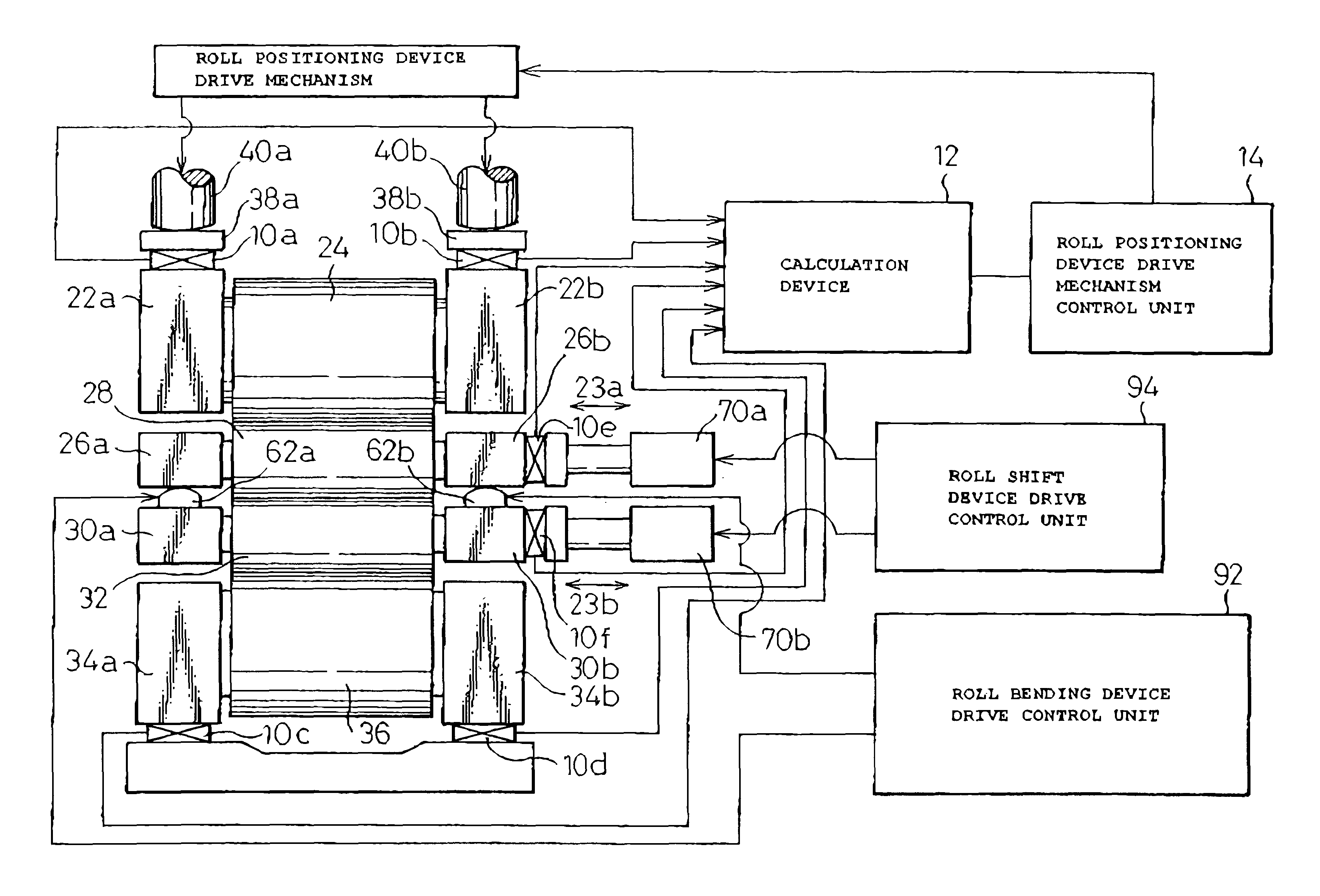
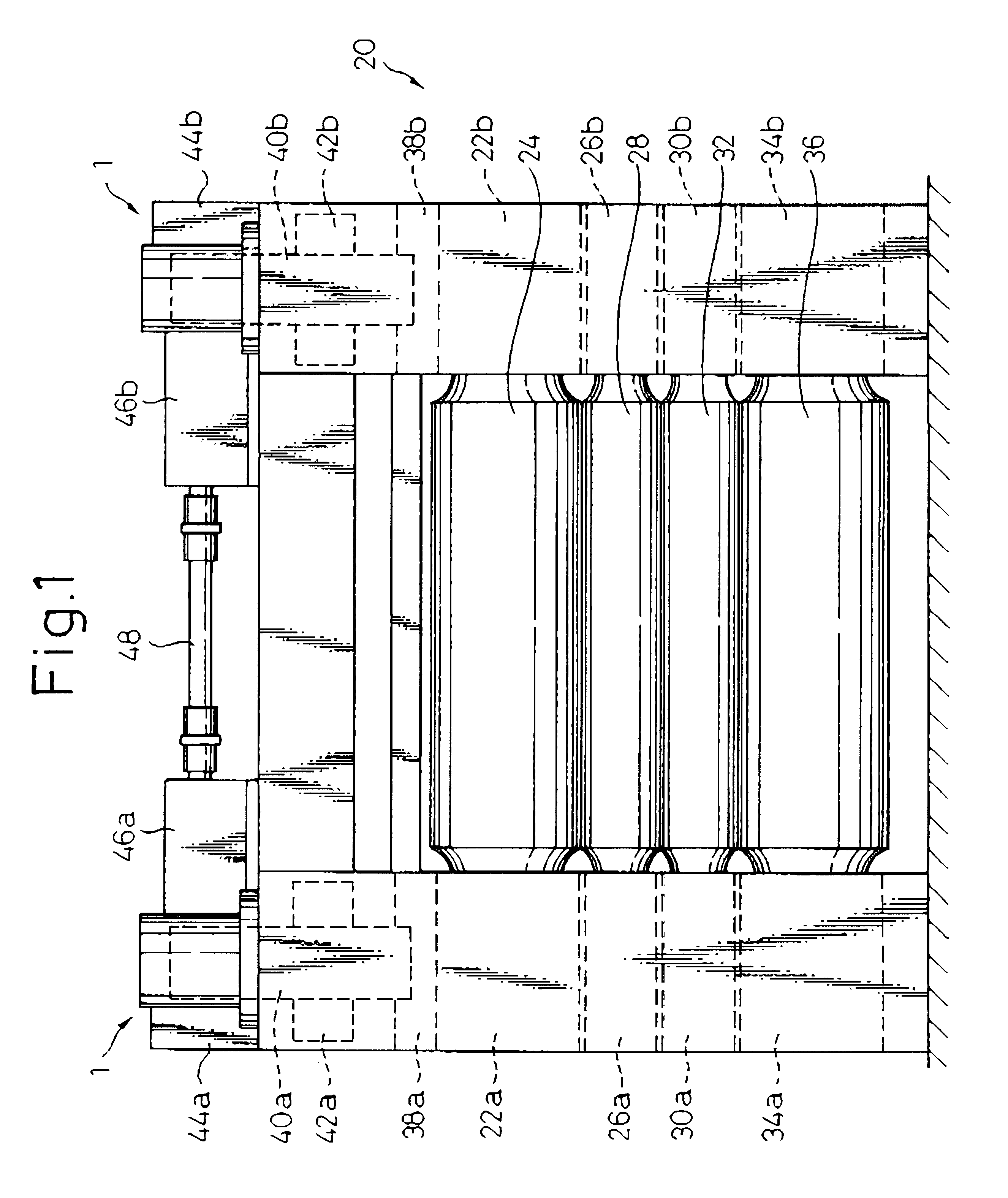
When the ratio of elongation on the work side and that on the drive side are different from each other, a defect, such as a camber, and a failure in the dimensional accuracy, such as wedge-shaped strip thickness occur.
Further, problems may be caused when a strip is rolled.
For example, (lateral) traveling or trail
crash of a workpiece to be rolled may be caused in the process of threading.
However, it is impossible to completely solve the above problems of defective quality such as camber and wedge-shaped strip thickness, and also it is impossible to completely solve the above problems of threading, such as (lateral) traveling and pinching, of a trailing end of a workpiece to be rolled.
However, the difference between the
load cell load of the rolling mill on the work side and that on the drive side includes various disturbances in addition to an influence caused by (lateral) traveling of the workpiece to be rolled.
However, in the case of rolling a long workpiece or in the case of tandem-rolling, even if leveling is not adjusted appropriately, (lateral) traveling is not caused in many cases because of the weight of the workpiece to be rolled on the upstream side of the rolling mill and also because of a condition of restriction of the workpiece by the rolling mill on the upstream side.
Therefore, according to the above methods disclosed in the Patent Publications, in the case of rolling a long workpiece or in the case of tandem-rolling, it is impossible to detect a quantity of (lateral) traveling although leveling is not adjusted appropriately.
For the above reasons, it is impossible to use any of the above methods as the most appropriate method of controlling the leveling.
When a quantity of (lateral) traveling is directly measured by the above methods, it is impossible to optimize leveling only by these methods.
Further, according to the above methods, a phenomenon occurring in the roll bite is not directly measured.
Therefore, the methods tend to be affected by disturbance, and furthermore a
delay is caused in the control of leveling, which is an essential defect of the methods.
However as described above, the difference between the rolling load on the work side and that on the drive side detected by the
load cell includes not only a quantity of (lateral) traveling of the workpiece to be rolled but also various disturbance.
For the above reasons, this thrust force becomes a serious disturbance with respect to the object of determing, by the difference between the load measured by the load cells of the rolling mill on the work side and that on the drive side,
asymmetry of the rolling
load distribution on the work and the drive side.
Therefore, it is very difficult to estimate the thrust force.
In this case, not only the above thrust force between the rolls but also the thrust force between the top and the bottom
work roll becomes disturbed.
When the thrust force acts between the rolls at this time as described above and disturbance is included in the difference between the load measured by the
load cell on the work side and the load measured by the load
cell on the drive side, it becomes impossible to conduct an accurate zero point adjustment of leveling, and this error of zero point adjustment is caused at all times when leveling is conducted after that.
Also in this case, the aforementioned thrust force generated between the rolls could be a serious
error factor.
For the above reasons, it is not easy to measure the thrust counterforces.
Therefore, explanations will be made under the condition that it is impossible to obtain a measured value of the thrust counterforces of the
backup roll.
Therefore, it becomes impossible to estimate a difference of the distribution of the linear load of the rolls between the work and the drive side.
However, in this case, when a roll forces is quickly changed by the
hydraulic cylinder, there is a possibility that a great error occurs in the measured value.
When the above type thrust reaction forces measuring device is used, a roll balance force acting on each roll or a frictional force in the axial direction of the roll caused by a roll
bending force could be a serious disturbance when a thrust reaction forces is measured.
In general, it is difficult to measure this frictional force itself.
Therefore, this frictional force becomes a factor of disturbance of the measured thrust counterforces.
However, since the chock of the top
work roll does not support the thrust force, the top
work roll chock is a little displaced in the direction of the thrust force together with the bottom work roll.
However, in some cases, it is impossible to control the crown profile of a rolled strip at a predetermined value by the above roll balance force or the roll
bending force.
However, in the case of a rolling mill having only the roll bending device as a control means for controlling a strip crown and flatness, there is a possibility that a predetermined strip crown and flatness can not be obtained when the above rolling method is adopted.
The above loads which are not symmetrical with respect to the upper and lower sides cannot be balanced only by the
internal forces of the rolling mill housings on the work and the drive side.
As a result, the load given to the housing on the work side can not be balanced by the single body of the housing on the work side.
Therefore, for example, it is possible to use an
overhead crane as it is, in which it is difficult to accurately measure the external force to be given.
Due to the moment received in this way, there is a possibility that a thrust force is generated by friction on a contact face of the calibration device with the roll of the rolling mill.
This thrust force causes a disturbance to the load
cell used for measuring a rolling load.
Therefore, this thrust force also causes a disturbance when the deformation characteristic is determined by giving a load asymmetrical with respect to the upper and lower sides which is an object of the method of calibration of the rolling mill.
However, even if the thrust force can be measured and the thrust force acting on the backup rolls can be measured, it is not clear how the measured thrust force has an influence on the load
cell load.
However, the
backup roll is given a
heavy load from not only the keeper strip but also the roll positioning devices and the roll balance device.
However, as described later, the present device of calibration is not necessarily used under the condition that the thrust force acting on the top roll and the thrust force acting on the bottom roll are balanced with each other.
However, not only the
resultant force of the thrust counterforces but also a frictional force in the vertical direction following this
resultant force acts between the above fixing members and the support member for supporting the thrust counterforces of the calibration device.


