
Resistive shunt ESD and EOS protection for recording heads

a technology of resistive shunt and recording head, which is applied in the direction of data recording, magnetic recording, instruments, etc., can solve the problems of deterioration of the transducer in reading and writing data, esd and eos protection, and buildup of electrostatic charges

Inactive Publication Date: 2002-06-04
IBM CORP
View PDF9 Cites 70 Cited by
  • Summary
  • Abstract
  • Description
  • Claims
  • Application Information

AI Technical Summary

Benefits of technology

The other objective of the present invention is to provide a method for protecting the (G)MR sensor from ESD and EOS damage but at the same time allow the (G)MR sensor element to be tested at various stages in the manufacturing process.
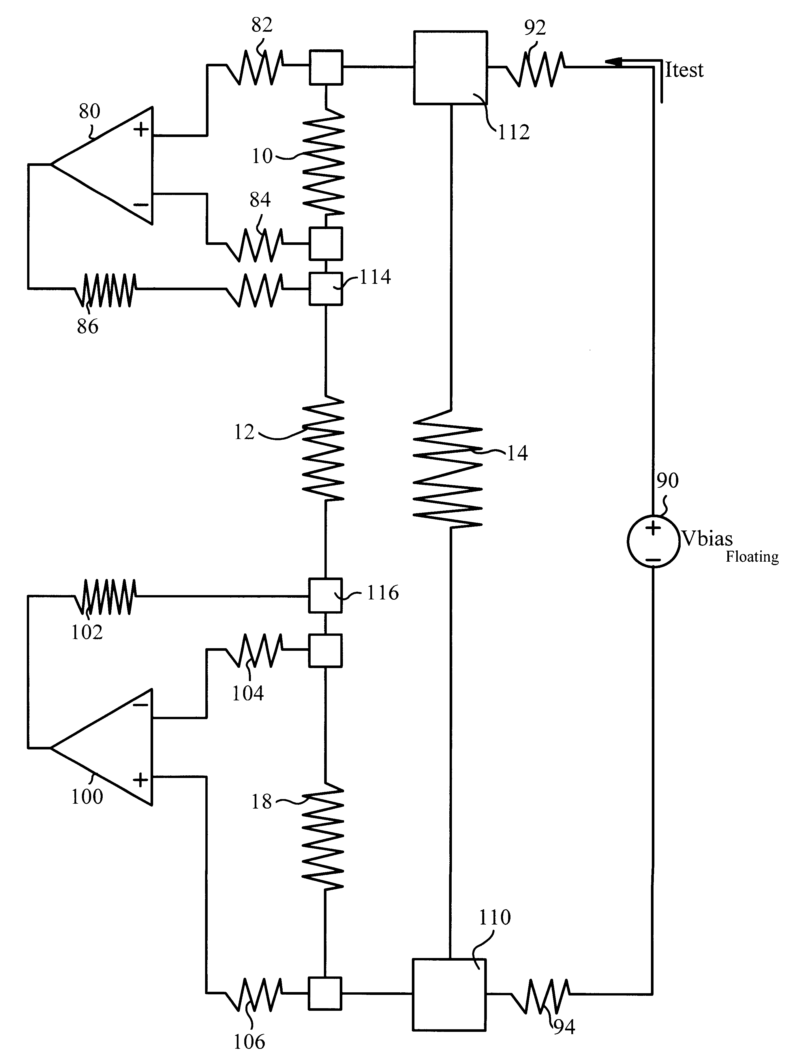
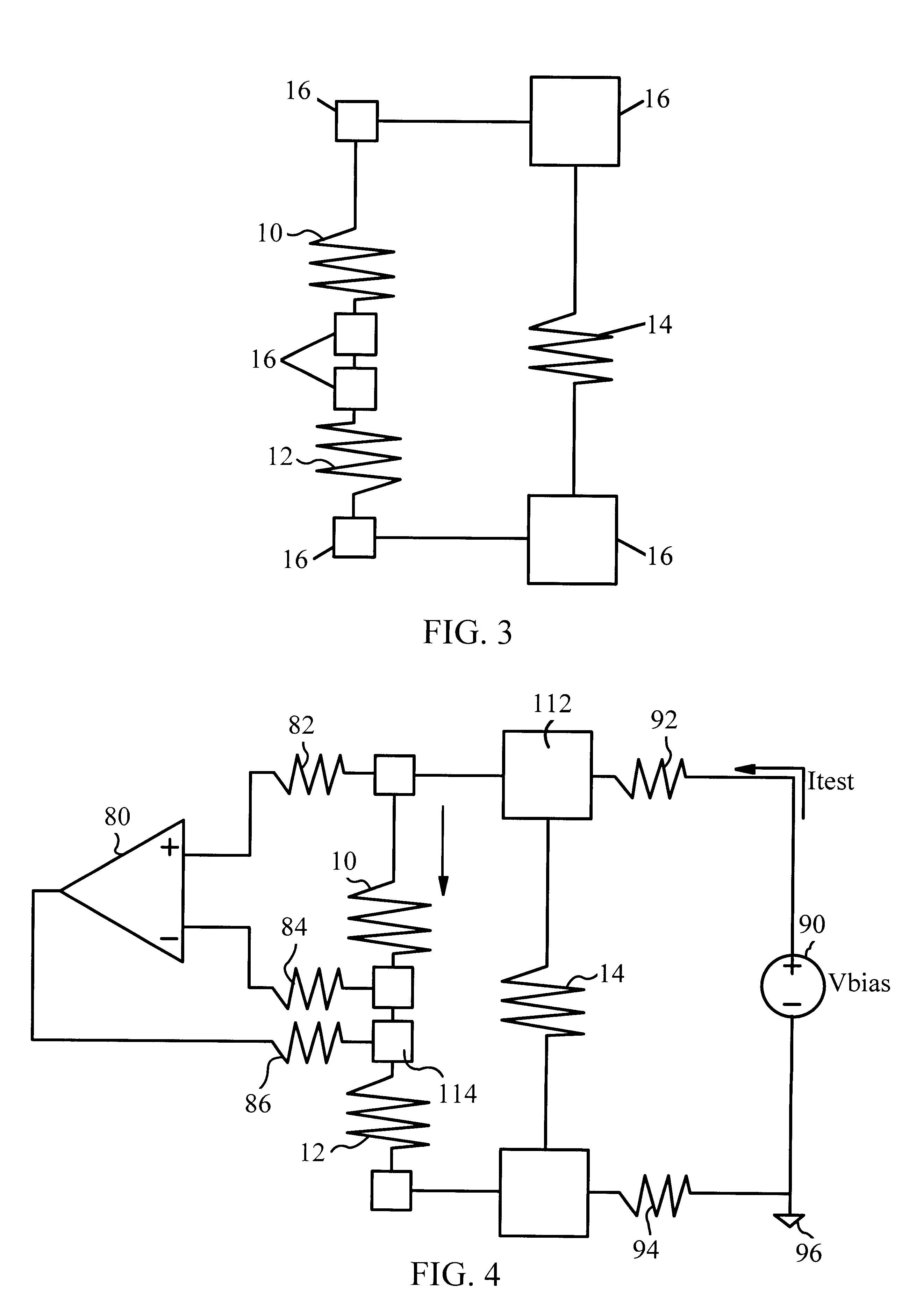
The present invention also provides a method that would allow the (G)MR sensor element to be tested at the desired stages during the manufacturing process. By using appropriate electronic circuitry, the low resistance bypass can be temporarily disabled, i.e. no current is allowed to flow through it, thereby allowing the (G)MR sensor element to be tested.

Problems solved by technology

A major problem that is encountered during manufacture, handling and use of magnetic recording transducers, referred to as heads, is the buildup of electrostatic charges on the various elements of a head or other objects which come into contact with the heads, particular heads of the thin film type, and the accompanying spurious discharge of the static electricity thus generated.
These static charges arc across the edge of the insulating layer between the magnetic pole tips and adjacent conductive layers which are exposed and positioned adjacent to the transducing gap at the air bearing surface facing the recording medium thus causing erosion of the pole tips and degradation of the transducer in reading and writing of data.
As described above, when an MR sensor is exposed to ESD, or even a voltage or current input larger than that intended under normal operating conditions, referred to as electrical overstress or EOS, the MR sensor and other parts of the head may be damaged.
This sensitivity to electrical damage is particularly severe for MR read sensors because of their relatively small physical size.
Discharge of voltages of only a few volts through such a physically small sensor, behaving like a resistor, is sufficient to produce currents capable of severely damaging or completely destroying the MR sensor.
The nature of the damage which may be experienced by an MR sensor varies significantly, including complete destruction of the sensor via melting and evaporation, contamination of the air bearing surface, generation of shorts via electrical breakdown, and milder forms of damage in which the head performance may be degraded.
However, both of these approaches have significant disadvantages.
This leaking current through the diode leads to shot noise, which will lower the signal to noise ratio of the readback process.
Diodes also introduce parasitic capacitance across the head, and from the head leads to the ground, which adversely affects the maximum readback bandwidth achievable with the head.
Moreover, modern generations of Giant Magnetoresistive (GMR) heads are so sensitive to ESD, the diode is not sufficiently forward biased to shunt enough current away from the MR sensor element even for low ESD voltages.
The problem with this technique is that it is no longer possible to test the MR head after the short is applied.
However, this method is difficult to realize, as switches require large amounts of real estate on the back of the slider, and the switching process requires low resistance shorting and re-shorting structures.

Method used


Image

  • Resistive shunt ESD and EOS protection for recording heads
  • Resistive shunt ESD and EOS protection for recording heads
  • Resistive shunt ESD and EOS protection for recording heads

Examples


Embodiment Construction

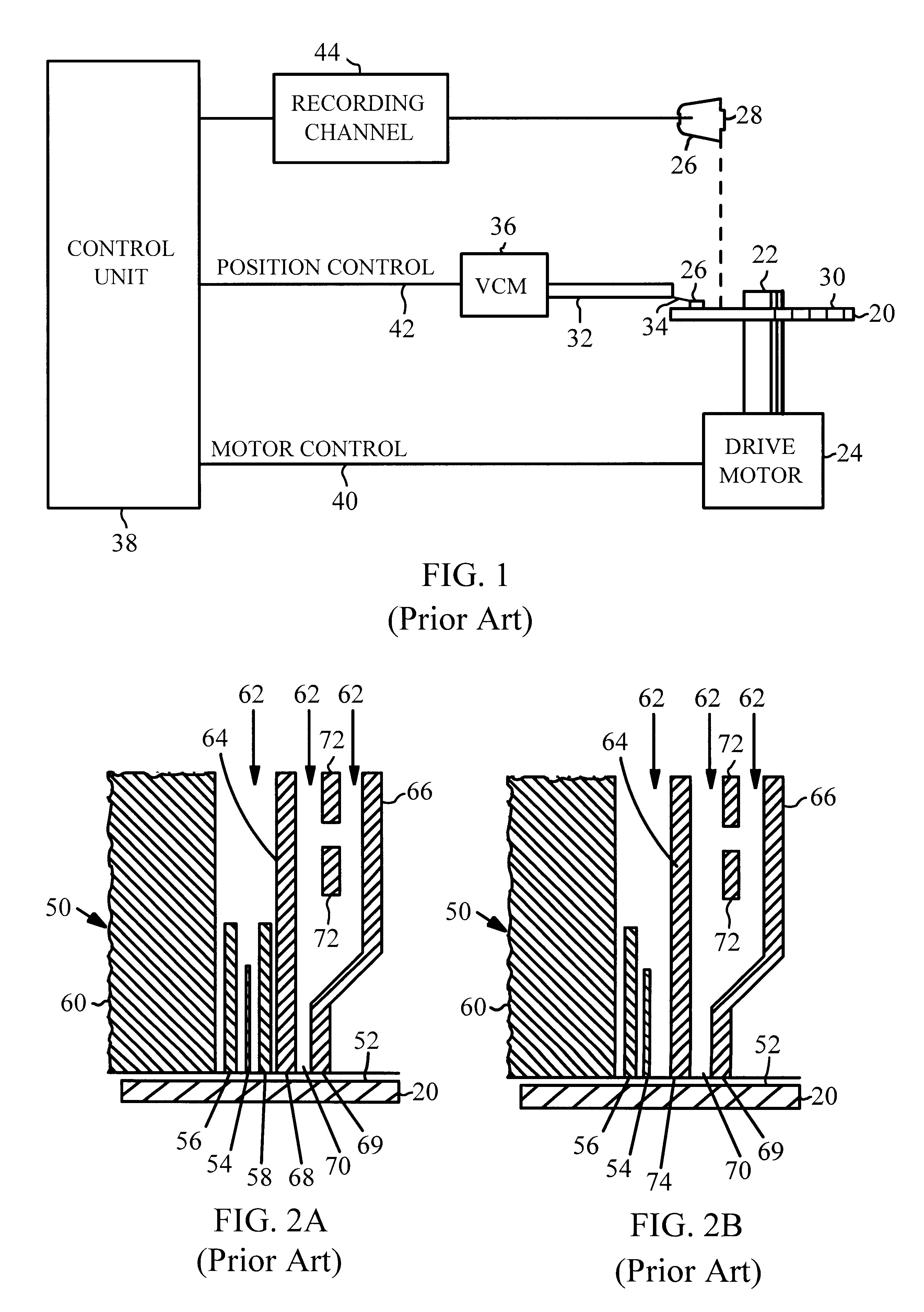
Although the invention is described as embodied in a magnetic disk storage system, the invention also applies to other magnetic recording systems and applications using a sensor to detect a magnetic field, such as magnetic tape recording systems for example. Referring to prior art FIG. 1, a magnetic disk storage system comprising at least one rotatable magnetic disk 20 is supported on a spindle 22 and rotated by a disk drive motor 24 with at least one slider 26 positioned on the disk 20. Each slider 26 supports one or more magnetic read / write transducers 28, typically referred to as read / write heads. The magnetic recording media on each disk is in the form of an annular pattern of concentric data tracks (not shown) on disk 20. As the disks rotate, the sliders 26 are moved radially in and out over the disk surface 30 so that the heads 28 may access different portions of the disk where desired data is recorded. Each slider 26 attaches to an actuator arm 32 by means of a suspension 34....


PUM


Abstract

In a magnetic read / write assembly, the magnetoresistive (G)MR sensor element is protected against electrostatic discharge (ESD) and electrical overstress (EOS) by using a low resistance bypass. The low resistance bypass shunts current away from the magnetoresistive sensor element during an ESD or EOS event. This low resistance bypass is made up of two or more resistors connected in series, and positioned in parallel to the magnetoresistive sensor element. The use of electronic circuitry to temporarily disable this low resistance bypass allows the magnetoresistive sensor element to be tested during manufacturing. The low resistance bypass is removed prior to placing the (G)MR head into operation in the magnetic storage system or at any other desired step in the manufacturing process.

Description

The present invention relates to electrical protection circuitry for magnetic disk drives and more particularly circuitry to protect against electrostatic discharge (ESD) and electrical overstress (EOS) in read / write transducers utilizing magnetoresistive read sensors.DESCRIPTION OF THE RELATED ARTMagnetic head disk drive systems have been widely accepted in the computer industry as a cost-effective form of data storage. In a magnetic disk drive system, a magnetic recording medium in the form of a disk rotates at high speed while a magnetic read / write transducer, referred to as a magnetic head, "flies" slightly above the surface of the rotating disk. The magnetic disk is rotated by means of a spindle drive motor. The magnetic head is attached to or formed integrally with a "slider" which is suspended over the disk on a spring-loaded support arm known as the actuator arm. As the magnetic disk rotates at operating speed, the moving air generated by the rotating disk in conjunction wit...

Claims


Application Information

Patent Timeline
IPC IPC(8): G11B5/39G11B5/40
CPCG11B5/3903G11B5/40Y10S977/934G11B5/39
Inventor KLAASSEN, ERNO HILBRAND
Owner IBM CORP
Learn More