Eureka AIR delivers breakthrough ideas for toughest innovation challenges, trusted by R&D personnel around the world.

Hologram laser unit and optical pickup device including the same

a laser unit and optical pickup technology, applied in the direction of optical beam sources, instruments, disposition/mounting of heads, etc., can solve the problems of increasing the size and manufacturing cost of the device, adversely affecting mass production, and the optical disk is no longer compatible with the optical disk having a substrate of a conventional thickness

Inactive Publication Date: 2002-05-14
SHARP KK
View PDF19 Cites 10 Cited by
  • Summary
  • Abstract
  • Description
  • Claims
  • Application Information

AI Technical Summary

Benefits of technology

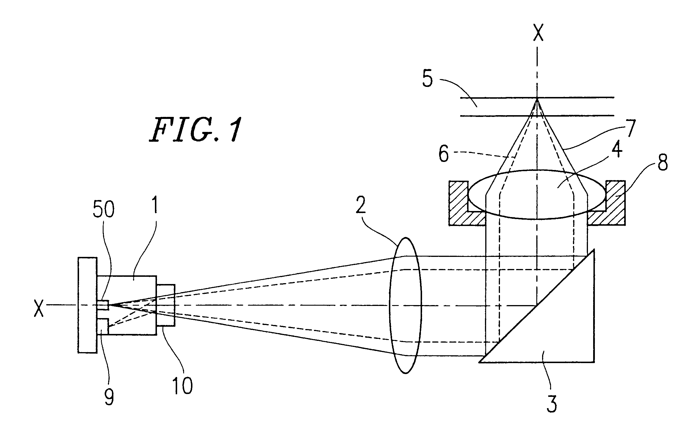
By providing the second hologram outside the first hologram in a positionally contiguous manner, the variation in the light amount of a converged light spot on the optical disk can be minimized despite possible shifts in the position of the objective lens during tracking.
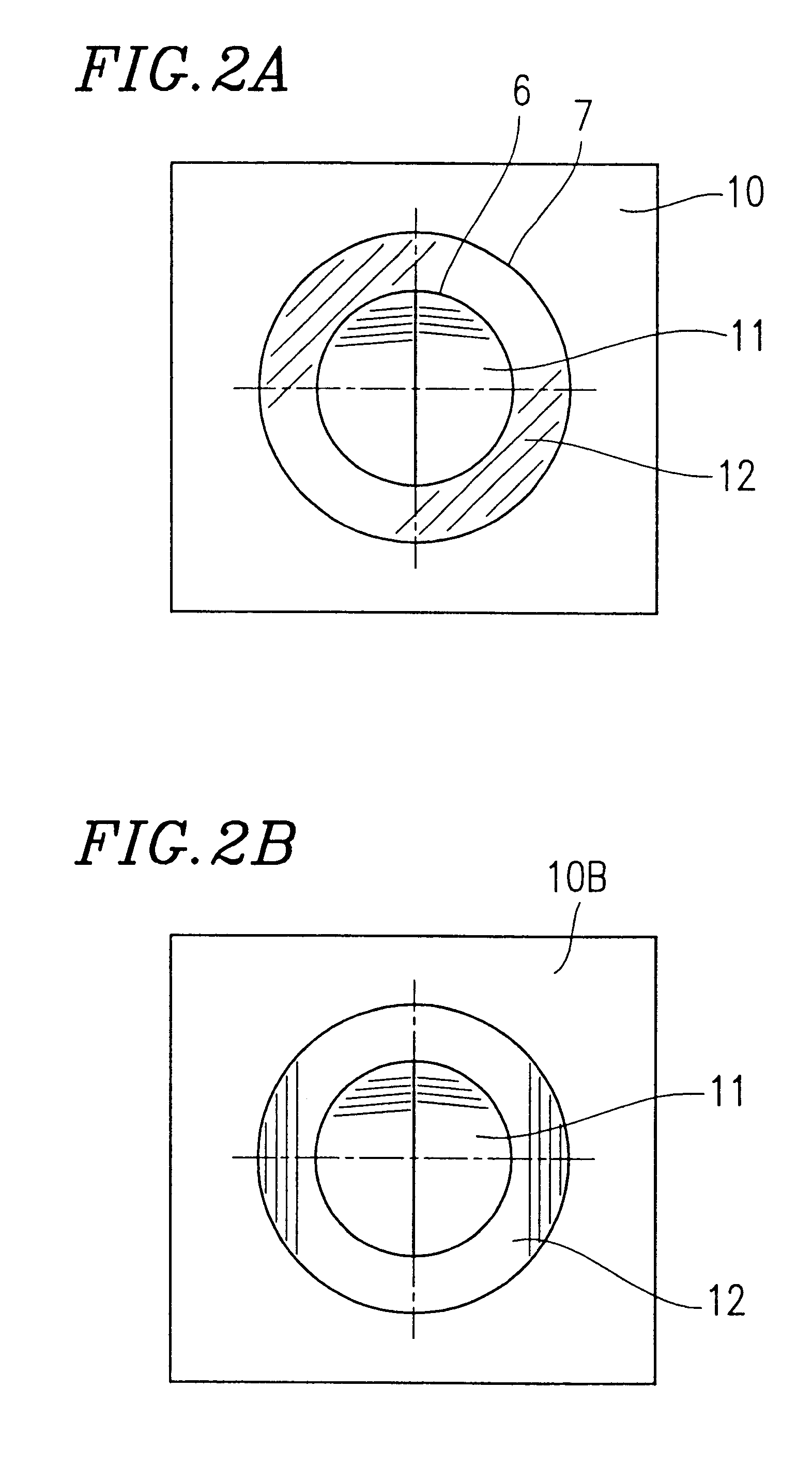
By providing the two types of holograms so that the respective diffraction directions thereof are substantially orthogonal with each other, the returning light diffracted by the second hologram (for compensating for the amount of transmitted light) can be prevented from becoming stray light that enters the photodetector of the hologram laser unit.
By providing the two types of holograms so that their respective pitches do not have substantial difference therebetween, there occurs no large difference between the amounts of transmitted light from the hologram laser unit into the optical disk, even when the two types of holograms are simultaneously processed. As a result, deterioration of the convergence characteristics on the optical disk can be prevented.
By providing an additional photodetector corresponding to the second hologram (for compensating for the amount of transmitted light) in the hologram laser unit, sufficient information signals can be secured even when reproducing an optical disk which calls for a larger numerical aperture than that is prescribed for the hologram laser unit.
By providing a photodetector corresponding to the second hologram so as to be divided into a plurality of portions substantially along the direction of a radius of an optical disk, it becomes possible to detect the shift amount of the objective lens.
Thus, the invention described herein makes possible the advantages of (1) providing a hologram laser unit which can perform recording and reproducing operations of information for multiple types of optical disks having different substrate thicknesses with the use of the same objective lens by providing a variable numerical aperture, without degrading the optical performance or requiring a complicated mechanism or resulting in an increased cost, and which provides excellent mass-productivity and reliability; and (2) providing an optical pickup device incorporating such a hologram laser unit.

Problems solved by technology

However, if the substrate thickness of the optical disk is reduced as described above, the optical disk is no longer compatible with optical disks having a substrate of a conventional thickness.
However, the various aforementioned conventional methods of changing the numerical aperture NA have the following problems.
The method in which the aperture restriction plate is placed in and out of the optical path requires a mechanism capable of highly precisely performing the insertion and retraction of the aperture restriction plate, resulting in an increase in the size and manufacturing cost of the device thereby adversely affecting mass production.
Moreover, since the insertion / retraction mechanism is required to be integrated and driven with the moving unit for the optical pickup, the mass of the moving unit is inevitably increased so as to degrade the servo performance of an actuator used for driving the moving unit.
Moreover, regardless of whether the liquid crystal plate is integrated with the moving unit or not, the liquid crystal materials contained in the liquid crystal plate are susceptible to a change in their characteristics (e.g., refractive index) due to a change in temperature.
Therefore, such a device may not exhibit the desired performance due to changes in the environmental conditions.
In addition, all of the above-described methods require an additional mechanism in the optical pickup device, likely causing drawbacks such as complicated configuration and increase in cost.

Method used


Image

  • Hologram laser unit and optical pickup device including the same
  • Hologram laser unit and optical pickup device including the same
  • Hologram laser unit and optical pickup device including the same

Examples


example 2

FIG. 4 is a schematic diagram illustrating a configuration of a hologram element 10C which may be incorporated in a hologram laser unit in an optical pickup device according to Example 2 of the present invention. FIG. 5 is a schematic diagram illustrating a functional relationship between the hologram element 10C in FIG. 4 and a photodetector 9B, in a hologram laser unit for use in the optical pickup device of Example 2.

In the photodetector 9B, light receiving elements 14 and 15 are provided for detecting information signals (including servo signals) on an optical disk. A light beam 6, which is a portion of reflected light from the optical disk which is diffracted by a detection hologram 11, enters the light receiving elements 14 and 15. A reproduction signal, a focus servo signal, and a tracking servo signal can be detected, for example, from the sum signal of the signals which are detected by the light receiving elements 14 and 15, the difference signal of the signals which are de...

example 3

An exemplary configuration of an optical pickup device according to Example 3 of the present invention will be described with reference to FIG. 8.

An optical pickup device shown in FIG. 8 includes two hologram laser units 1 and 21 having light sources 50 and 70 of different wavelengths, respectively, and an objective lens 4, and is capable of performing information recording / reproduction for optical disks 5 and 5' having different (i.e., two in the illustrated example) substrate thicknesses. For example, the hologram laser unit 1 can include a light source 50 having a wavelength of 780 nm while the hologram laser unit 21 can include a light source 70 with a wavelength of 650 nm. Furthermore, assuming that the optical disks 5 and 5' to be detected include substrates which are 0.6 mm and 1.2 thick, respectively, the suitable numerical apertures corresponding to the optical disks 5 and 5' are 0.6 and 0.45, respectively.

The configuration shown in FIG. 8 will be explained in more detail.

W...

example 4

Another exemplary configuration of an optical pickup device according to Example 4 of the present invention will be described with reference to FIG. 10. The same components as those in FIG. 8 are indicated by the same reference numerals as those used therein, and the descriptions thereof are omitted.

When a light beam is to be converged on two types of optical disks 5 and 5' having different substrate thicknesses by using a single objective lens 4, spherical aberration may occur depending on the substrate thickness. For example, when an objective lens which is suitable for an optical disk 5 having a 0.6 mm-thick substrate is employed to converge a light beam on an optical disk 5' having a substrate of 1.2 mm thick, a spherical aberration corresponding to the difference between the substrate thicknesses (i.e., 0.6 mm) occurs.

The optimum numerical aperture of the objective lens for the optical disk 5' having a 1.2 thick substrate is as small as 0.45, so that the amount of resulting abe...


PUM


Abstract

A hologram laser unit to be used for performing recording and reproducing operations of information for an optical disk, includes a light source, a photodetector, and a hologram element which are formed integrally with each other. The hologram element includes: a first hologram for detecting information signals from the optical disk, the first hologram being provided in an area having an effective diameter corresponding to a numerical aperture suitable for the optical disk; and a second hologram for compensating for only a transmitted light amount of light traveling toward the optical disk from the light source, the second hologram being provided contiguously outside the first hologram.

Description

1. Field of the InventionThe present invention relates to an optical pickup device for use in an optical disk apparatus for optical recording / reproduction of information on recording media such as optical disks, and a hologram laser unit to be incorporated in such an optical pickup device. More particularly, the present invention relates to an optical pickup device which is capable of performing accurate recording / reproducing operations for a plurality of types of optical disks having different recording densities; and a hologram laser unit to be incorporated in such an optical pickup device.2. Description of the Related ArtIn recent years, optical disks capable of recording signals representing a large amount of information at a high density have been utilized in a number of fields including audio, video, and computer applications. Compact disks (CDs), video disks, mini-disks (MDs), and magneto-optical disks for computers, which are widely commercially available now, generally empl...

Claims


Application Information

Patent Timeline
IPC IPC(8): G11B7/135G11B7/13G11B7/125G11B7/00G11B7/08G11B7/12G11B7/123G11B7/1275G11B7/131G11B7/1353G11B7/1381G11B7/1392
CPCG11B7/123G11B7/1275G11B7/131G11B7/1381G11B7/13922G11B7/1353G11B2007/0006G11B7/08
Inventor SAKAI, KEIJINAKATA, YASUO
Owner SHARP KK
Why Eureka
Eureka Blog
Learn More