Detector of an oscillation stopping and an apparatus for executing a treatment after the detection of an oscillation stopping
a technology of oscillation stopping and detection apparatus, which is applied in the direction of instruments, generating/distributing signals, data conversion, etc., can solve the problems of wasting a long time, unable to communicate with other micro computers, and unable to detect the overflow of the eight bit timer
- Summary
- Abstract
- Description
- Claims
- Application Information
AI Technical Summary
Problems solved by technology
Method used
Image
Examples
first embodiment
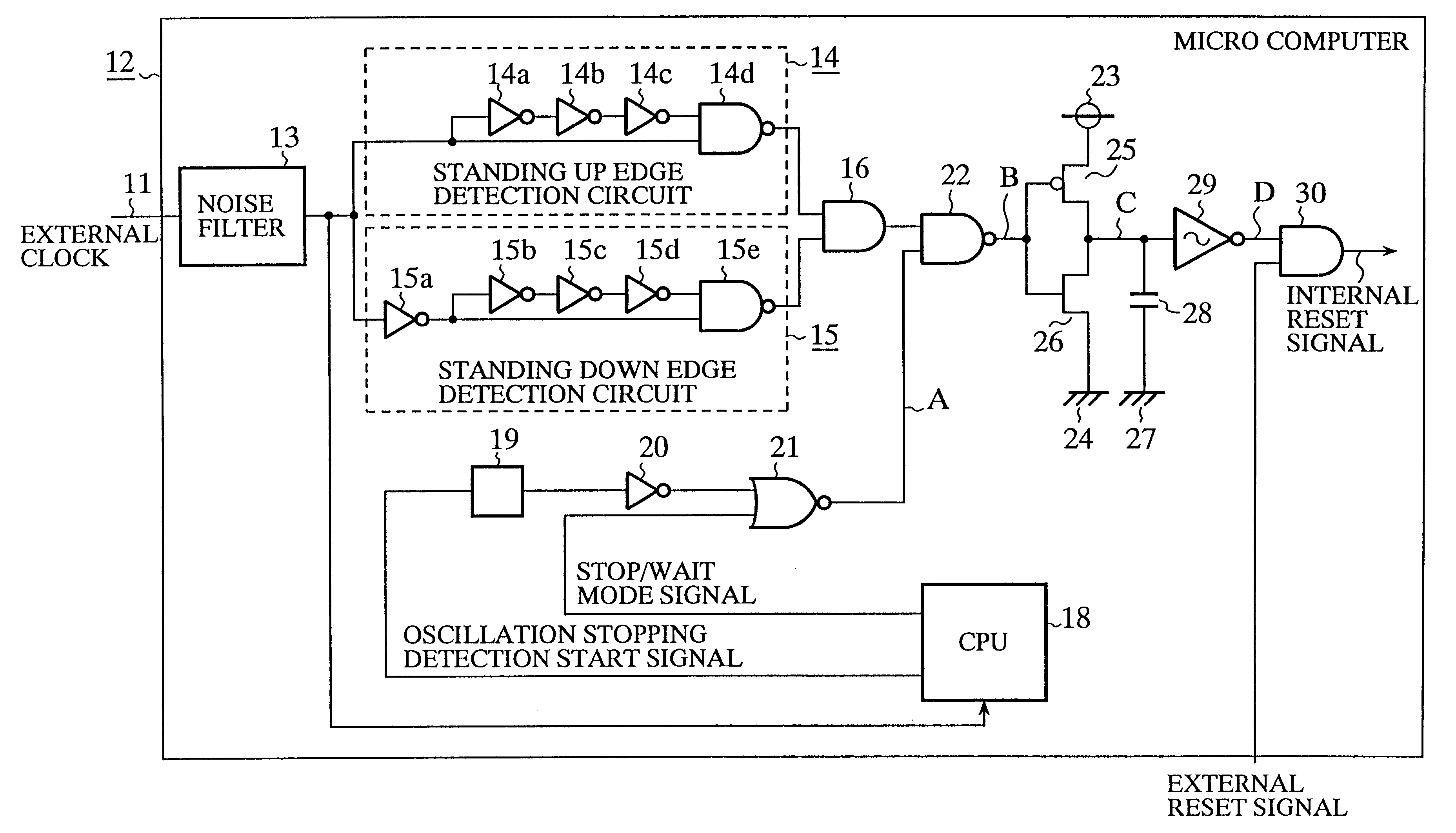
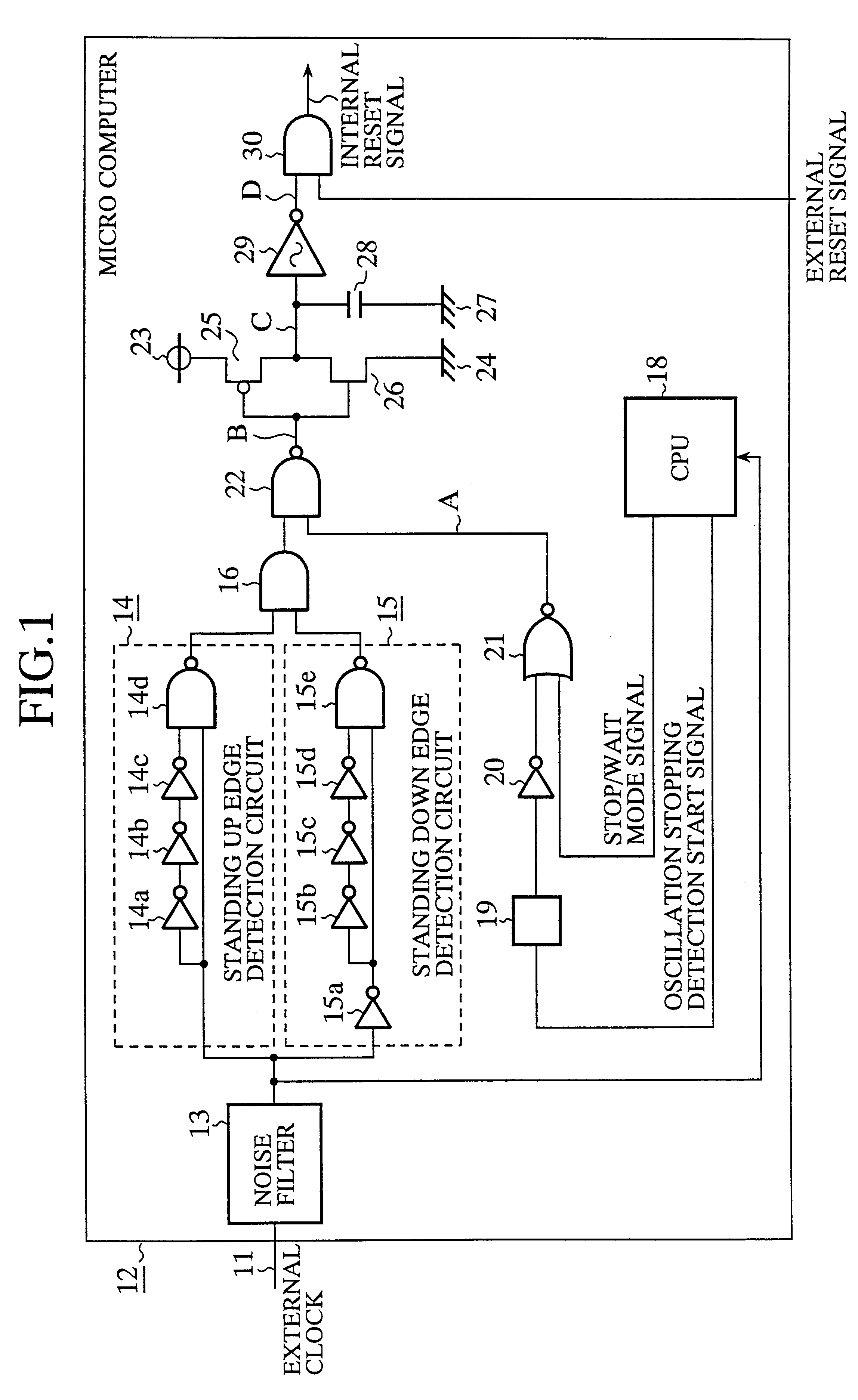
FIG. 1 shows a block diagram of a detector of an oscillation stopping according to the present invention. Reference numeral 11 denotes a clock signal supplied from an external oscillator through an external clock input terminal. Reference numeral 12 denotes a micro computer formed on a semiconductor substrate. A noise filter 13 eliminates noises in the external clock signal. A standing up edge detection circuit 14 for detecting the standing up edge of the external clock signal 11 is a one shot pulse generating circuit comprised of inverters 14a-14c and a NAND circuit 14d. A standing down edge detection circuit 15 for detecting the standing down edge of the external clock signal is a one shot pulse generating circuit comprised of inverters 15a-15d and a NAND circuit 15e. An AND circuit 16 calculates the AND logic of the outputs of the standing up edge detection circuit 14 and the standing down edge detection circuit 15 to output a one shot pulse at the moment when the standing up edg...
embodiment 2
FIG. 4 shows a schematic diagram of an apparatus for executing a treatment after the detection of the oscillation stopping according to the second embodiment of the present invention.
Reference numeral 40 denotes a micro computer formed on a semiconductor substrate. The framed portion 41 is substantially identical with the detector of an oscillation stopping according to the first embodiment of the present invention.
However the framed portion comprises a NOR circuit 42 with three input terminals, and a Schmitt circuit 43 (oscillation stopping signal generating circuit), which outputs a signal of "H", when the oscillation of the external clock stops. The AND circuit 30 in FIG. 1 is not included in the framed portion. CPU 45 is not identical with the CPU 18 in the first embodiment, its functions is different from the latter, and will be explained later.
A framed portion 51 is a ring oscillator, which is actuated by the oscillation stopping signal from the Schmitt circuit 43, and generat...
case 1
tection starting signal is "H" (the detection of the oscillation stopping is allowed), and the stop / wait signal is "L" (the stop / wait mode is not selected). In this state, the node A is "H".
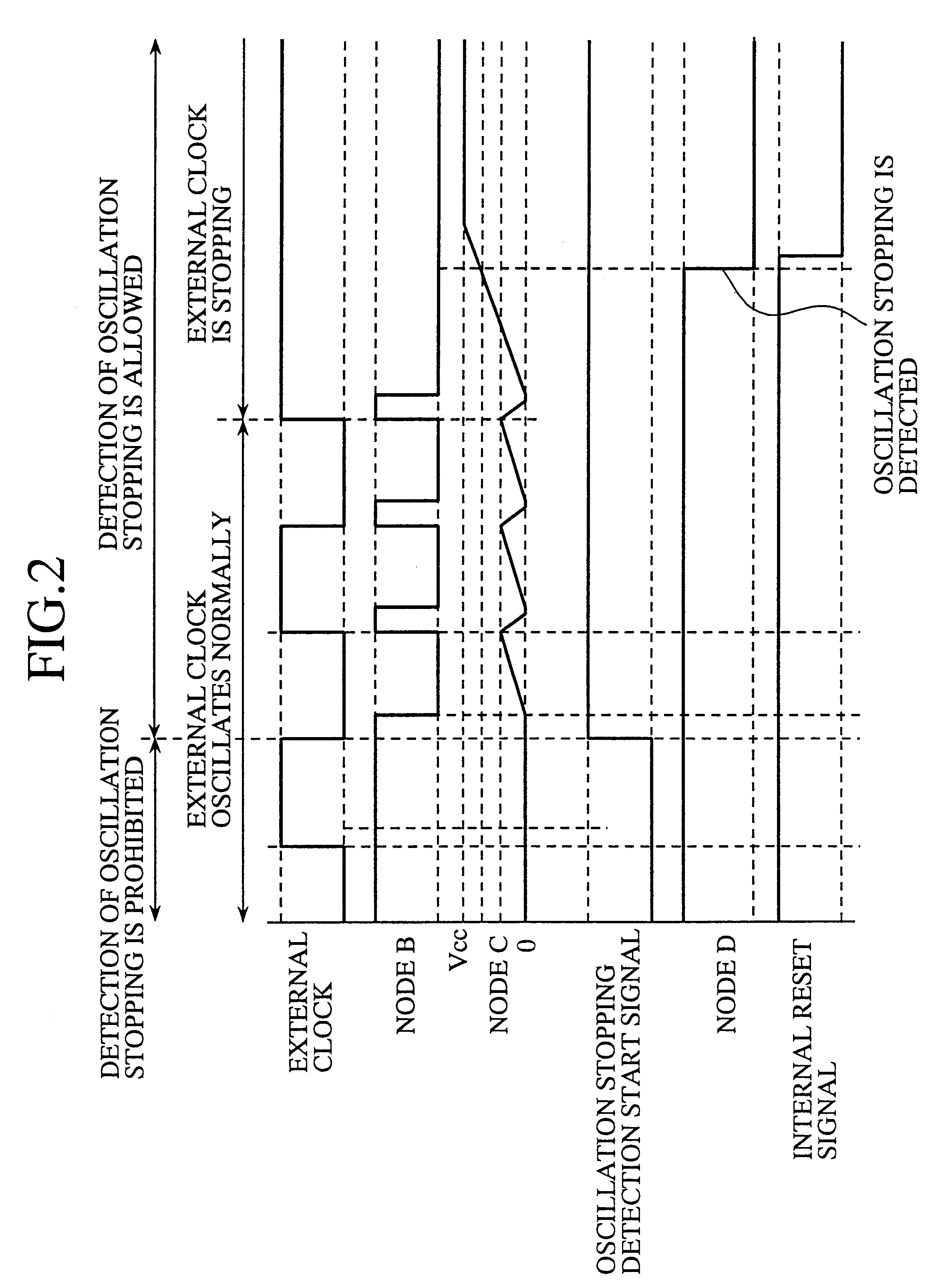
When the external clock 11 oscillates normally, while the detection of the oscillation stopping is allowed, as shown in FIG. 5, one shot pulse of "H" level appears at the node B for each standing up edge and for each standing down edge of the external clock 11. The voltage at the node C is a sawtooth wave form. Therefore the voltage at the node C does not exceed a predetermined threshold voltage of the Schmitt circuit 43, and the Schmitt circuit 43 outputs a signal of "L" to the node D, which implies that the oscillation of the external clock 11 is normal.
As a result, the ring oscillator 51 is not actuated, and the clock exchanging circuit 52 continues to supply the external clock 11, as a system clock .phi., to the micro computer 40. The standing up edge detection circuit 53 does not generate th...
PUM
 Abstract
Description
Claims
Application Information
 - R&D
- Intellectual Property
- Life Sciences
- Materials
- Tech Scout
- Unparalleled Data Quality
- Higher Quality Content
- 60% Fewer Hallucinations
Browse by: Latest US Patents, China's latest patents, Technical Efficacy Thesaurus, Application Domain, Technology Topic, Popular Technical Reports.
© 2025 PatSnap. All rights reserved.Legal|Privacy policy|Modern Slavery Act Transparency Statement|Sitemap|About US| Contact US: help@patsnap.com


